Novel cubbyhole capable of photographing
A file holder and a new type of technology, applied in the camera, electrical components, camera body and other directions, can solve the problem of difficult to meet the requirements of electronic file imaging, and achieve the effect of low cost, reasonable and compact overall structure
- Summary
- Abstract
- Description
- Claims
- Application Information
AI Technical Summary
Problems solved by technology
Method used
Image
Examples
Embodiment 1
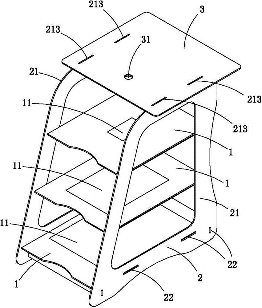
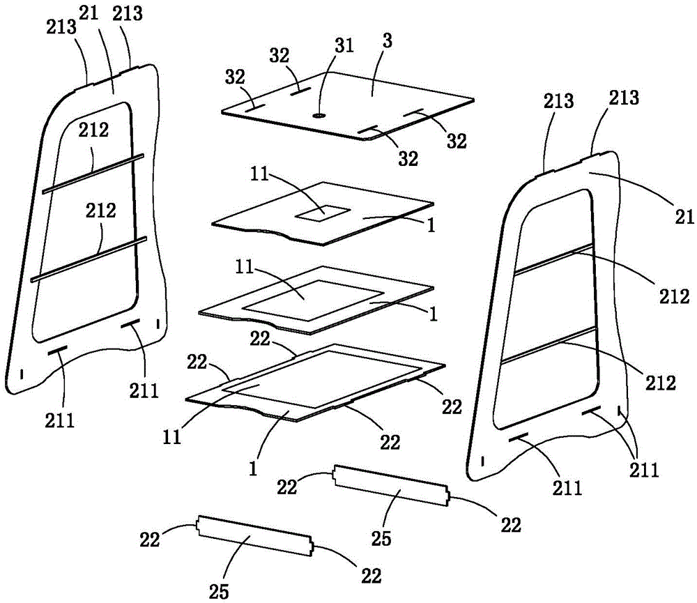
[0021] Figure 1 to Figure 2 A first embodiment of the invention is shown in which, figure 1 It is a schematic diagram of a three-dimensional structure of the first structure of the present invention; figure 2 for figure 1 An exploded view of the photographable file holder shown.
[0022] Present embodiment is a kind of novel photographable file rack, see Figure 1 to Figure 6 As shown, a frame body 2 is included, and the frame body includes three pallets 1 for placing documents to be photographed and a camera board 3 for placing a mobile phone or a tablet computer. The three pallets are divided into three layers from top to bottom, and the photo board is set directly above the uppermost pallet; each pallet and photo board are set horizontally, and the camera board is set directly opposite the center of each pallet below. The shooting hole 31.
[0023] The shooting hole 31 is generally preferably slightly larger than the diameter of the camera of the mobile phone or the ...
Embodiment 2
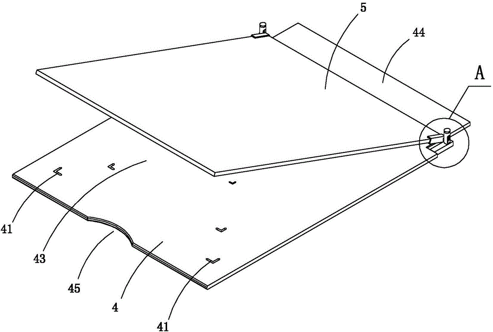
[0033] Figure 3 to Figure 6 A second embodiment of the invention is shown in which, image 3 It is a schematic diagram of a three-dimensional structure of the flattening mechanism in the second structure of the present invention; Figure 4 for image 3 Partial enlarged schematic diagram of A; Figure 5 for image 3 A partial exploded view of the flattening mechanism shown; Figure 6 for Figure 5 The partial enlarged schematic diagram of B.
[0034]This embodiment is basically the same as Embodiment 1, except that in this embodiment, a flattening mechanism for flattening the paper to be photographed is also provided on the pallet; the flattening mechanism includes a backing plate 4 and a transparent pressing plate 5, transparent The pressing plate is rotatably connected with the backing plate, the backing plate is arranged on the supporting plate, and the transparent pressing plate is crimped on the backing plate. This is because in most cases, there are creases on the...
Embodiment 3
[0041] Figure 7 to Figure 10 A third embodiment of the invention is shown in which, Figure 7 It is a schematic diagram of a three-dimensional structure of the flattening mechanism in the third structure of the present invention; Figure 8 for Figure 7 Partial enlarged schematic diagram at C; Figure 9 for Figure 7 A partial exploded view of the flattening mechanism shown; Figure 10 for Figure 9 The partial enlarged schematic diagram in D.
[0042] This embodiment is basically the same as Embodiment 2, the difference is: see Figure 7 to Figure 10 , this embodiment does not set the clamping piece. In this embodiment, a positioning hole 46 is provided on both sides of the backing plate, and a positioning piece 91 is provided on the bottom wall of the backing plate at the location of the positioning hole. The positioning part 912 at the bottom; the positioning hole is also provided with a positioning slide tube 92 and a hook spring 93. The hook spring includes an up...
PUM
 Abstract
Description
Claims
Application Information
 - R&D
- Intellectual Property
- Life Sciences
- Materials
- Tech Scout
- Unparalleled Data Quality
- Higher Quality Content
- 60% Fewer Hallucinations
Browse by: Latest US Patents, China's latest patents, Technical Efficacy Thesaurus, Application Domain, Technology Topic, Popular Technical Reports.
© 2025 PatSnap. All rights reserved.Legal|Privacy policy|Modern Slavery Act Transparency Statement|Sitemap|About US| Contact US: help@patsnap.com


