Locking and unlocking mechanism for folding wing

A technology of unlocking mechanism and folding wings, applied in the direction of projectiles, offensive equipment, weapon types, etc., can solve the problems of square locking blocks prone to breakage, not meeting overall requirements, and small occupied space, so as to achieve small occupied space and structure. Simple and easy to maintain

Active Publication Date: 2014-11-26
THE GENERAL DESIGNING INST OF HUBEI SPACE TECH ACAD
View PDF5 Cites 12 Cited by
  • Summary
  • Abstract
  • Description
  • Claims
  • Application Information

AI Technical Summary

Problems solved by technology

This solution occupies a small space and unlocks quickly, but requires a large unlocking force, which does not meet the overall requirements, and will bear a large impact when the wing surface is deployed, and the square locking block is prone to breakage, so the unlocking mechanism must be improve the structure

Method used


Image

  • Locking and unlocking mechanism for folding wing
  • Locking and unlocking mechanism for folding wing
  • Locking and unlocking mechanism for folding wing

Examples


Embodiment Construction

[0023] In order to make the object, technical solution and advantages of the present invention clearer, the present invention will be further described in detail below in conjunction with the accompanying drawings and embodiments. It should be understood that the specific embodiments described here are only used to explain the present invention, not to limit the present invention. In addition, the technical features involved in the various embodiments of the present invention described below can be combined with each other as long as they do not constitute a conflict with each other.

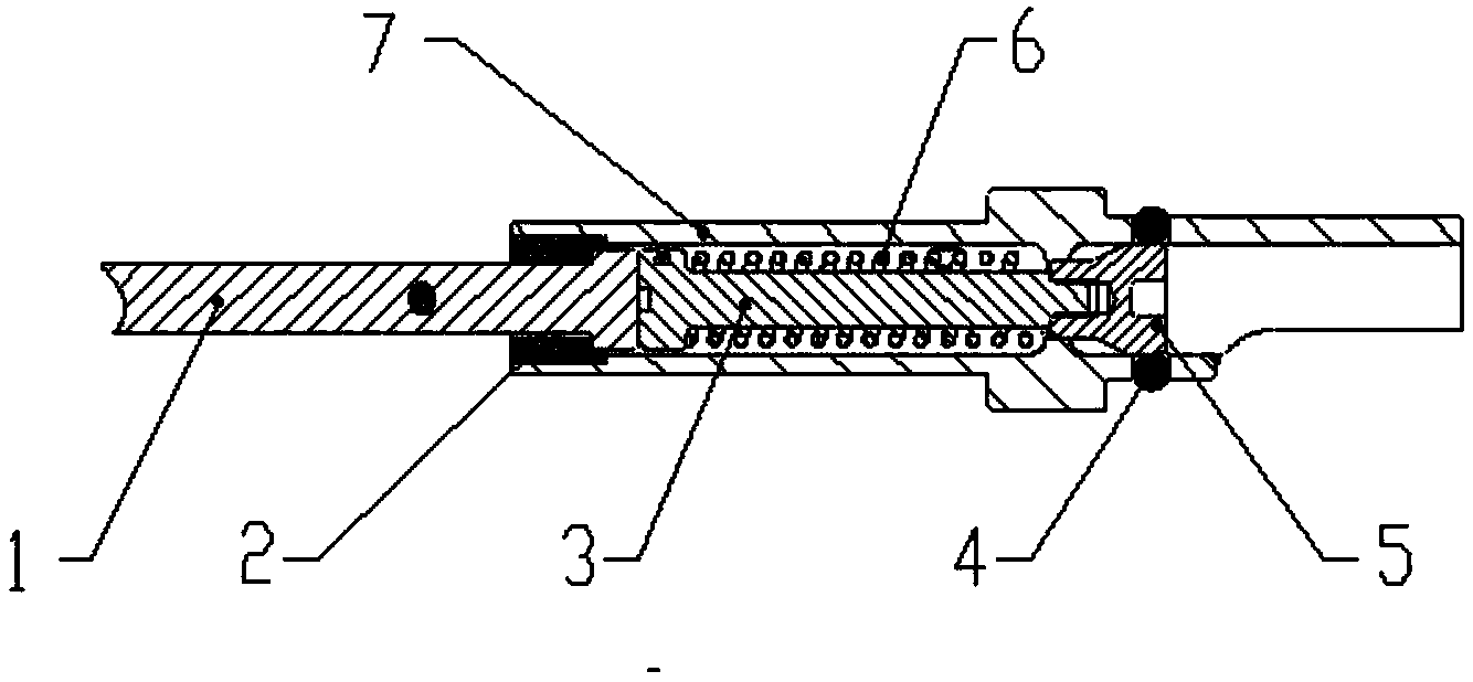
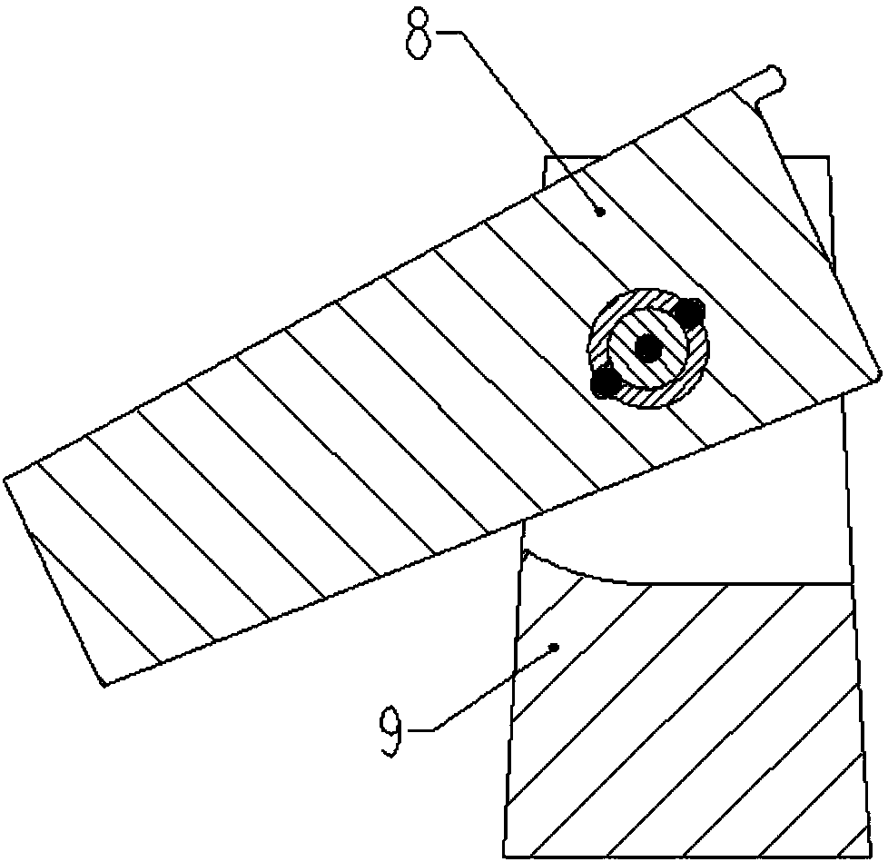
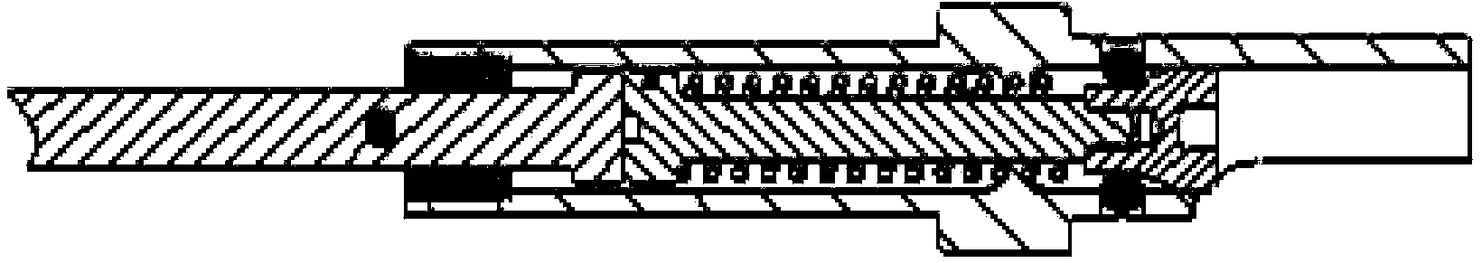
[0024] See Figure 1~6 , the locking and unlocking mechanism for folding wings in this embodiment is arranged between the outer wing 8 and the inner wing 9, including the actuator 7 placed between the inner and outer wings, the outer push rod 1, the inner push rod 3, the ball 4. Compression spring 6 and plug 5.

[0025] The outer cylinder wall at the right end of the actuator 7 is symmetricall...


PUM


Abstract

The invention discloses a locking and unlocking mechanism for a folding wing. The locking and unlocking mechanism is structurally characterized in that an inner push rod is placed in an action cylinder in the axial direction, an end cap is connected to the right end of the inner push rod in a sleeved mode, and the end face of the left end of the inner push rod is in contact with an outer push rod; a compression spring is arranged between the outer portion of the inner push rod and the inner wall of the action cylinder in a sleeved mode; two through holes for containing balls are symmetrically formed in the outer cylinder wall at the right end of the action cylinder, and the positions, corresponding to the two through holes, of an outer wing are provided with two arc grooves; when the push rod is pushed to move rightwards, the end cap is moved away from the through holes of the action cylinder, the balls are extruded into the through holes under the action of the torque of an inner wing and the outer wing and enter an inner cavity of the action cylinder, and therefore a smooth rotating shaft is formed by the action cylinder; the push rod is loosened, the inner push rod drives the end cap to move leftwards through the compression spring, the end cap moves to the through holes, the balls are ejected out of the through holes so that the arc grooves of the outer ring and the action cylinder are coaxial, the balls are ejected into the grooves, and the rotating shaft with a protrusion is formed by the action cylinder. By means of the locking and unlocking mechanism, unlocking force is reduced, the service life is prolonged, using is convenient, and occupied space is small.

Description

technical field [0001] The invention relates to the technical field of locking mechanisms, in particular to a locking and unlocking mechanism for folding wings. Background technique [0002] In order to meet the design requirements of the new generation of tactical missiles, a series of measures have been taken at home and abroad to reduce the space size of the missiles, including wing folding and miniaturization of the rudder surface. Due to the large size of the wings in the space of the missile, the use of folded wings can greatly reduce the loading space of the missile without affecting the tactical performance of the missile, and improve the number of bombs loaded and the transportation efficiency. [0003] During storage and transportation, the wings are folded to reduce the wingspan. When the missile is launched, the wings automatically unfold to the normal position. The function of the unlocking mechanism is to lock the folding wings and unlock them under external e...

Claims


Application Information

Patent Timeline
Patent Type & Authority Applications(China)
IPC IPC(8): F42B10/14
Inventor 信傲卢迪汪文龙杨攀桑希军王博哲孙利华
Owner THE GENERAL DESIGNING INST OF HUBEI SPACE TECH ACAD
Why Eureka
Try Eureka