Flexible touch substrate and touch display device
A flexible touch and touch display technology, applied in instruments, nonlinear optics, optics, etc., can solve the problems of thick touch screen, difficult in-cell touch technology, low sensitivity, etc.
- Summary
- Abstract
- Description
- Claims
- Application Information
AI Technical Summary
Problems solved by technology
Method used
Image

Examples
Embodiment 1
[0035] Such as figure 1 As shown, the embodiment of the present invention provides a flexible touch substrate, the flexible touch substrate includes a flexible substrate and a touch sensing unit, the touch sensing unit includes two layers of sensing layers, wherein at least one sensing layer is located on the flexible inside the substrate.
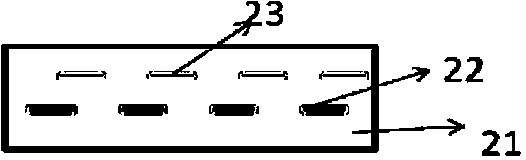
[0036] Specifically, the two sensing layers are respectively a first sensing layer 22 and a second sensing layer 23, and both the first sensing layer 22 and the second sensing layer 23 are located inside the flexible substrate 21, wherein, In this embodiment, the first sensing layer 22 and the second sensing layer 23 are located at different levels inside the flexible substrate 21 .
[0037] The manufacturing method of the flexible touch substrate in this embodiment is as follows:
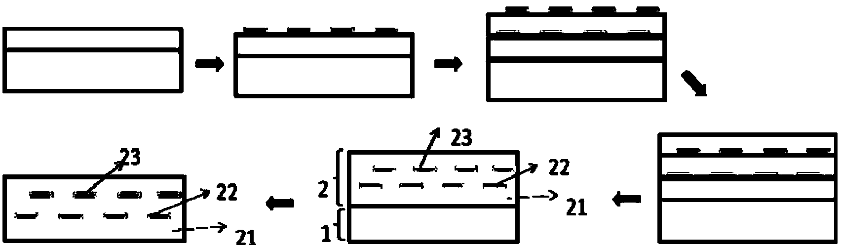
[0038] Such as figure 2 As shown, firstly, a layer of PI liquid is coated on a carrier plate (such as glass, quartz, plastic), then dried and prepared on t...
Embodiment 2
[0041] Such as image 3 As shown, the difference between this embodiment and the first embodiment is that the first sensing layer 22 and the second sensing layer 23 in this embodiment are located on the same layer inside the flexible substrate 21 .
[0042] The manufacturing method of the flexible touch substrate in this embodiment is as follows:
[0043] First, coat a layer of PI liquid on the glass carrier, then dry it and prepare the first sensing layer and the second sensing layer of touch sensing on it, the first sensing layer and the second sensing layer are located on the In the same layer, the first sensing layer is the metal guiding layer in the first direction, and the second sensing layer is the metal guiding layer in the second direction, wherein the direction of the metal guiding layer in the first direction and the metal guiding layer in the second direction are mutually crossing, Then apply PI liquid, dry and sinter to obtain the structure of the touch sensing ...
Embodiment 3
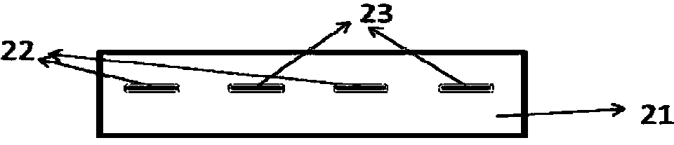
[0046] Such as Figure 4 As shown, the difference between this embodiment and Embodiment 1 is that one of the two sensing layers in this embodiment is located inside the flexible substrate, and the other sensing layer is located on the outer surface of the flexible substrate. superior. For example, the first sensing layer 22 is located inside the flexible substrate, while the second sensing layer 23 is located on the upper surface of the flexible substrate.
[0047] The manufacturing method of the flexible touch substrate in this embodiment is as follows:
[0048] First, coat a layer of PI liquid on the glass carrier, then dry it and prepare the first sensing layer in the touch sensing unit on it, then coat the PI liquid, dry and sinter, and then put on the second layer of PI film The second sensing layer is then prepared, and finally, the flexible substrate is peeled off from the glass carrier to obtain a structure in which the touch sensing part is inside the flexible subs...
PUM
 Abstract
Description
Claims
Application Information
 - Generate Ideas
- Intellectual Property
- Life Sciences
- Materials
- Tech Scout
- Unparalleled Data Quality
- Higher Quality Content
- 60% Fewer Hallucinations
Browse by: Latest US Patents, China's latest patents, Technical Efficacy Thesaurus, Application Domain, Technology Topic, Popular Technical Reports.
© 2025 PatSnap. All rights reserved.Legal|Privacy policy|Modern Slavery Act Transparency Statement|Sitemap|About US| Contact US: help@patsnap.com