Anti-slip bus handle device

A technology for public transportation and buses, applied in transportation and packaging, special positions of vehicles, vehicle components, etc., to solve problems such as slippage

Inactive Publication Date: 2014-12-03
费志勤
View PDF5 Cites 0 Cited by
  • Summary
  • Abstract
  • Description
  • Claims
  • Application Information

AI Technical Summary

Problems solved by technology

Ordinary bus handles have a smooth surface, and when the bus turns, accelerates, or brakes, passengers' hands tend to slip off the handle

Method used


Image

  • Anti-slip bus handle device

Examples


Embodiment Construction

[0009] The present invention will be further described now in conjunction with accompanying drawing. These drawings are all simplified schematic diagrams, which only illustrate the basic structure of the present invention in a schematic manner, so they only show the configurations related to the present invention.

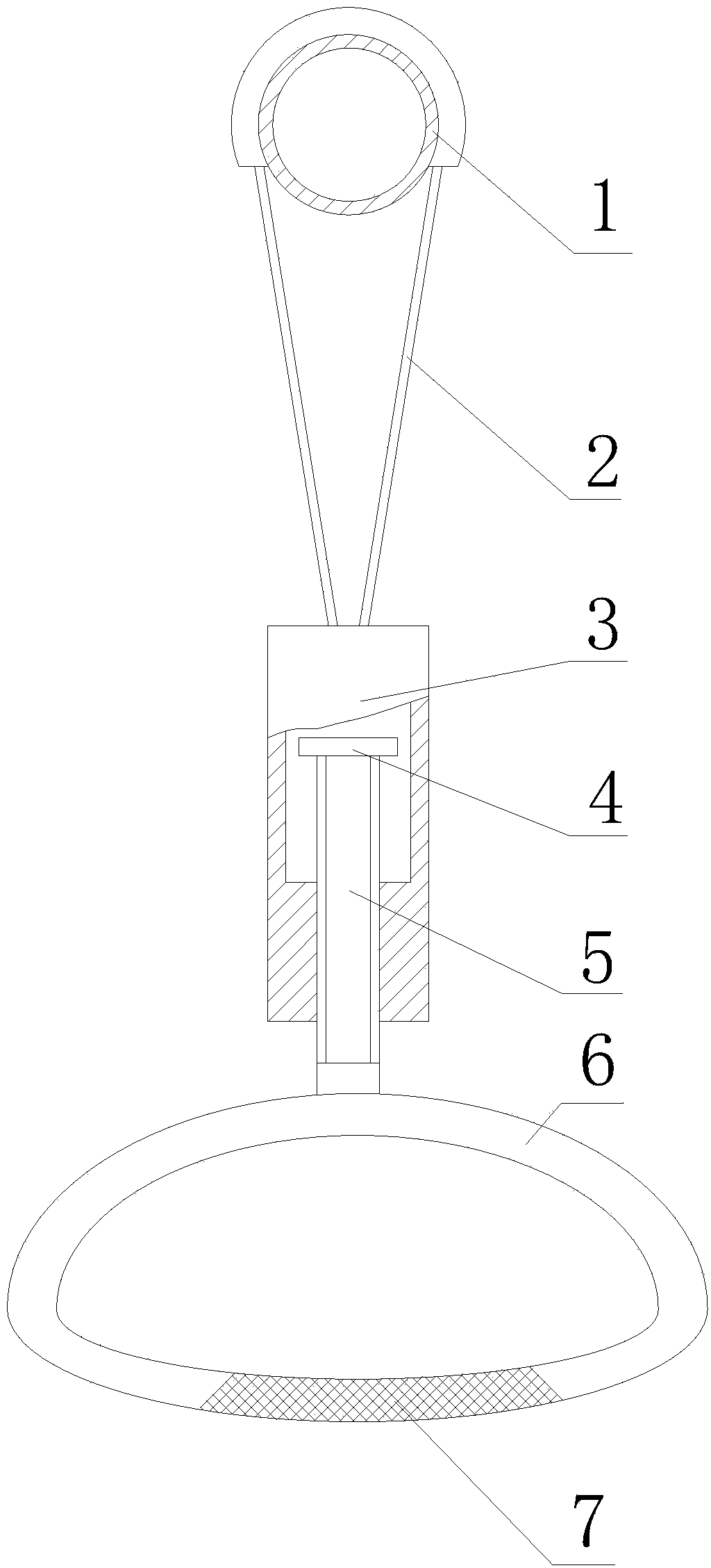
[0010] Such as figure 1 A kind of anti-slip type bus handle device shown is connected with the bus cross bar 1, and comprises a ring handle 6 connected successively from bottom to top, a connecting body 3, and a connecting belt 2 that surrounds the bus cross bar 1. There is a screw hole and a cavity in the connecting body 3, and the upper end of the ring handle 6 is fixed with a screw 5 threadedly connected with the screw hole and extending into the cavity. The baffle plate 4 that moves up and down in the cavity, the thread of the screw rod 5 is a double-start thread, and the ring handle 6 is distributed with grid-like protrusions 7 where the passenger's fingers a...


PUM


Abstract

The invention discloses an anti-slip bus handle device. The anti-slip bus handle device is connected with a bus cross bar and comprises a ring-shaped handle, a connecting body and a connecting belt wound around the bus cross bar, wherein the ring-shaped handle, the connecting body and the connecting belt are sequentially connected from bottom to top. A screw hole and a cavity are formed in the connecting body. A screw which is connected with the screw hole in a threaded mode and extends into the cavity is fixed to the upper end of the ring-shaped handle. A baffle capable of moving vertically along with the screw in the cavity is fixed to the end, in the cavity, of the screw. Threads of the screw are double-ended threads. Netted protrusions are distributed at the portion, grabbed by the fingers of passengers, of the ring-shaped handle.

Description

technical field [0001] The invention relates to an anti-skid bus handle device. Background technique [0002] When the bus is walking, in order to ensure the safety of riding, the standing passengers often need to pull the handle in the handle device suspended under the cross bar. Ordinary bus handles have a smooth surface, and when the bus turns, accelerates, or brakes, passengers' hands tend to slip off the handle. Contents of the invention [0003] The technical problem to be solved by the present invention is to overcome the deficiencies in the prior art and provide an anti-slip bus handle device. [0004] The technical solution adopted by the present invention to solve its technical problems is: a non-slip bus handle device connected to the bus bar, including ring handles connected sequentially from bottom to top, a connecting body, and a handle surrounding the bus bar. The connecting belt has a screw hole and a cavity in the connecting body, and the upper end of th...

Claims


Application Information

Patent Timeline
Patent Type & Authority Applications(China)
IPC IPC(8): B60N3/02
Inventor 费志勤
Owner 费志勤
Why Eureka
Try Eureka