Eureka AIR delivers breakthrough ideas for toughest innovation challenges, trusted by R&D personnel around the world.

Stainless steel pipe welding device and welding method thereof

A stainless steel tube and welding device technology, applied in auxiliary devices, welding equipment, auxiliary welding equipment, etc., can solve the problems of affecting welding quality, deteriorating welding seam quality and performance, laborious manual rotation, etc., to improve welding quality and flexible use. , The effect of easy spraying

Pending Publication Date: 2021-10-15
太仓金泰莱金属制品有限公司
View PDF9 Cites 0 Cited by
  • Summary
  • Abstract
  • Description
  • Claims
  • Application Information

AI Technical Summary

Problems solved by technology

Nitrogen and water vapor in the atmosphere enter the molten pool, and defects such as pores, slag inclusions, and cracks will be formed in the weld during the subsequent cooling process, deteriorating the quality and performance of the weld
[0003] There is an existing patent (CN110052753A) and a stainless steel pipe welding device. This patent enables the anti-oxidant nozzle to spray the weld anti-oxidant on the welded stainless steel pipe in time; Automatically spray a layer of anti-oxidant on the surface of stainless steel pipe welds to avoid the unevenness of stainless steel pipe welds due to severe oxidation. However, the device cannot ensure that two sets of stainless steel pipes are welded at the same time. When welding, because the welding seam is circular, the stainless steel round pipe needs to be rotated when the welding reaches a certain length. At the same time, as the welding line grows, the welder needs to change his posture, and welding in an uncomfortable posture will greatly affect the welding quality. It is very laborious to rely solely on manual rotation, and at the same time, it faces two common welding placements of stainless steel round tubes, namely horizontal welding and right-angle welding.

Method used


Image

  • Stainless steel pipe welding device and welding method thereof
  • Stainless steel pipe welding device and welding method thereof
  • Stainless steel pipe welding device and welding method thereof

Examples


specific Embodiment 1

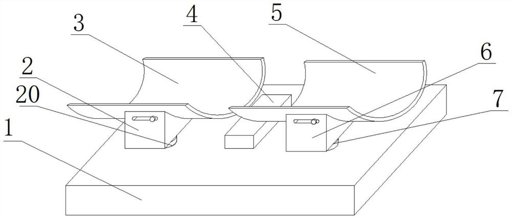
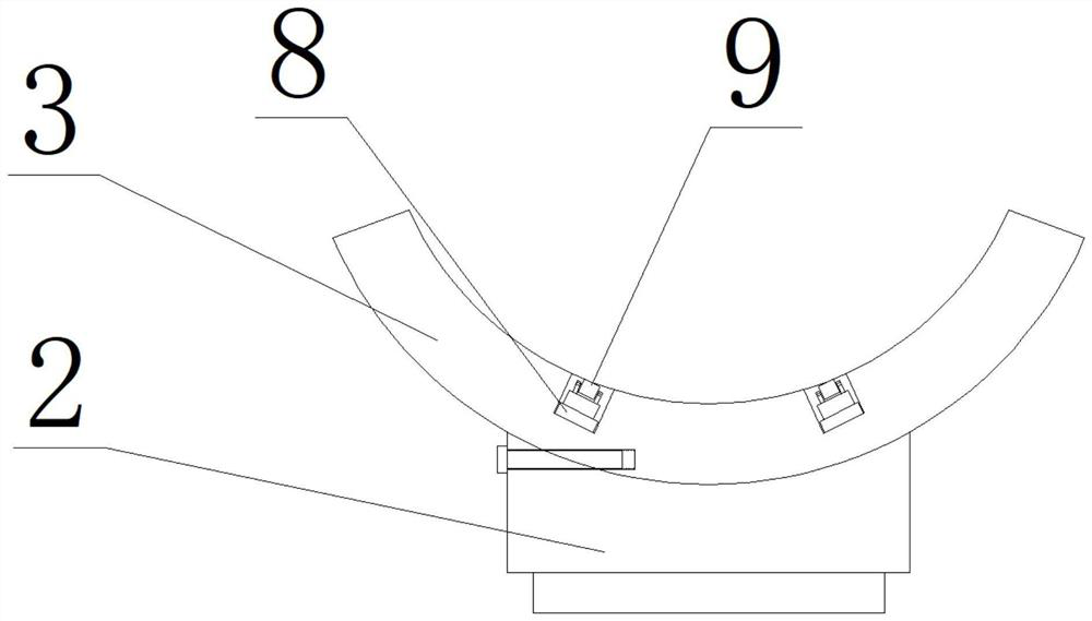
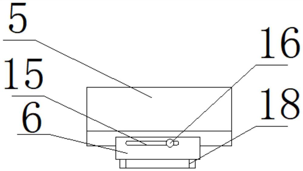
[0032] see Figure 1-5 , the present invention provides a technical solution: including a bottom plate 1, a left shell 2 and a right shell 6, a housing 4 is fixedly installed in the middle of the top surface of the bottom plate 1, a left ring 17 is fixedly installed on the left side of the top surface of the bottom plate 1, A right ring 7 is fixedly installed on the right side of the top surface of the bottom plate 1, a first arc plate 3 is placed on the top surface of the left shell 2, a second arc plate 5 is placed on the top surface of the right shell 6, and the first arc plate 5 is placed on the top surface of the right shell 6. There are cavities equally spaced on both sides of the bottom of the inner wall of the plate 3, an electric push rod 8 is installed on the bottom of the inner wall of the cavity, a roller 9 is installed on the top of the electric push rod 8, and a chute 15 is opened on the top of the outer wall of the right shell 6 , a sliding rod 16 is slidably in...

specific Embodiment 2

[0034]The present invention provides a technical solution: a stainless steel pipe welding device and its welding method, including a bottom plate 1, a left shell 2 and a right shell 6, a shell 4 is fixedly installed in the middle of the top surface of the bottom plate 1, and the top of the bottom plate 1 The left ring 17 is fixedly installed on the left side of the surface, the right ring 7 is fixedly installed on the right side of the top surface of the bottom plate 1, the first arc plate 3 is placed on the top surface of the left shell 2, and the first arc plate 3 is placed on the top surface of the right shell 6. The second arc plate 5, the two sides of the bottom of the inner wall of the first arc plate 3 are equidistantly provided with a cavity, the bottom of the inner wall of the cavity is equipped with an electric push rod 8, and the top of the electric push rod 8 is equipped with a roller 9. The top of the outer wall of the right shell 6 is provided with a chute 15, and...


PUM


Abstract

The invention relates to the technical field of stainless steel pipe welding, and discloses a stainless steel pipe welding device and a welding method thereof. The stainless steel pipe welding device comprises a bottom plate, a left shell and a right shell, a shell is fixedly installed in the middle of the top face of the bottom plate, a left ring is fixedly installed on the left side of the top face of the bottom plate, and a right ring is fixedly installed on the right side of the top face of the bottom plate; a first arc plate is placed on the top face of the left shell, a second arc plate is placed on the top face of the right shell, cavities are formed in the two sides of the bottom of the inner wall of the first arc plate at equal intervals, electric push rods are installed at the bottoms of the inner walls of the cavities, rollers are installed at the top ends of the electric push rods, a sliding groove is formed in the top of the outer wall of the right shell, a sliding rod is slidably installed in the sliding groove, and the tail end of the sliding rod is screwed corresponding to the bottom of a second sliding plate. According to the device, a worker can be conveniently assisted in rotating two groups of circular pipes, it is guaranteed that a welder conducts welding work in a comfortable state, meanwhile, the device can be flexibly applied, it is guaranteed that the device is suitable for horizontal welding and right-angle welding, and the functionality is higher.

Description

technical field [0001] The invention relates to the technical field of stainless steel pipe welding, in particular to a stainless steel pipe welding device and a welding method thereof. Background technique [0002] Metal welding, according to the characteristics of its process, can be divided into three categories: fusion welding, pressure welding and brazing; in the process of fusion welding, if the atmosphere is in direct contact with the high-temperature molten pool, the oxygen in the atmosphere will oxidize the metal and various alloying elements. Nitrogen and water vapor in the atmosphere enter the molten pool, and defects such as pores, slag inclusions, and cracks will be formed in the weld during the subsequent cooling process, deteriorating the quality and performance of the weld. [0003] There is an existing patent (CN110052753A) and a stainless steel pipe welding device. This patent enables the anti-oxidant nozzle to spray the weld anti-oxidant on the welded sta...

Claims


Application Information

Patent Timeline
Patent Type & Authority Applications(China)
IPC IPC(8): B23K37/00B23K37/053B23K101/06
CPCB23K37/00B23K37/0538B23K2101/06
Inventor 黄雪枫张霞徐永争
Owner 太仓金泰莱金属制品有限公司
Why Eureka
Eureka Blog
Learn More