Cleaning device for spinning rotors

A technology of cleaning device and rotor, which is applied to spinning machines, open-end spinning machines, and continuously wound spinning machines, etc., to achieve the effects of large pivot distance, low-cost structure, and reliable cleaning.

Active Publication Date: 2020-05-15
SAURER GERMANY GMBH & CO KG
View PDF10 Cites 0 Cited by
  • Summary
  • Abstract
  • Description
  • Claims
  • Application Information

AI Technical Summary

Problems solved by technology

[0012] A disadvantage in the cleaning device according to EP1327708B1 is that different cleaning heads have to be used for different rotor shapes in order to achieve adequate cleaning

Method used


Image

  • Cleaning device for spinning rotors
  • Cleaning device for spinning rotors
  • Cleaning device for spinning rotors

Examples


Embodiment Construction

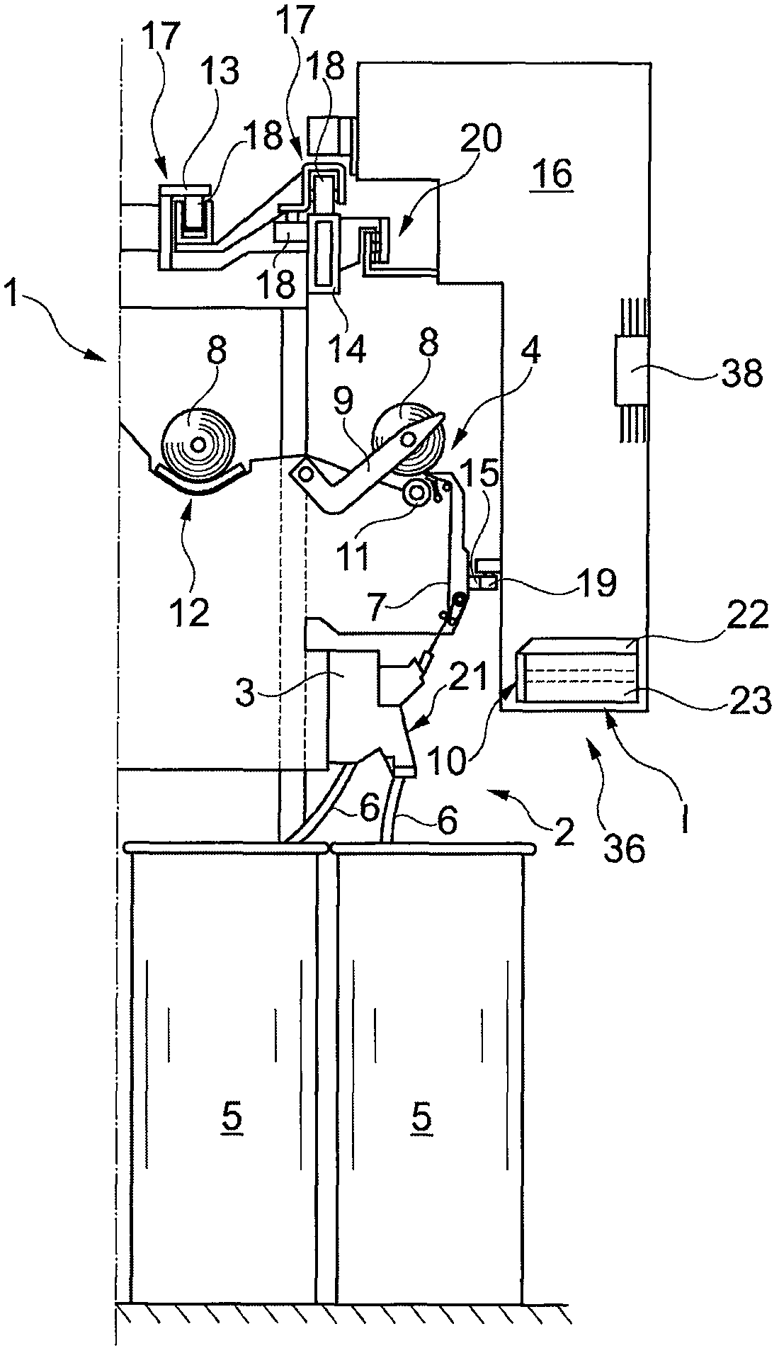
[0047] exist figure 1 A part of a rotor spinning machine known per se is shown in , which is marked with 1 . Such a rotor spinning machine 1 has a number of stations 2 each of which is equipped with a spinning box 3 and a winding device 4 .

[0048] In the spin box 3 , the fiber sliver 6 fed into the spinning can 5 is spun into a yarn 7 , which is then wound into a cross-wound bobbin 8 on a winding device 4 .

[0049] As shown, the winding device 4 is equipped with a creel 9 for rotatably holding empty bobbins or cross-wound bobbins 8 and a winding drum 11 for driving the cross-wound bobbins.

[0050] The fiber sliver opening mechanism 21 is located below the spinning box 3 . Behind the creel 9 there is a cross-wound bobbin discharge 12 along the length of the machine, whereby the cross-wound bobbins 8 produced are conveyed to a transfer station or the like arranged at the end of the machine.

[0051] On or on the rotor spinning machine 1 , the maintenance unit 16 is arrang...


PUM


Abstract

The invention relates to a cleaning device 10 for a spinning rotor 31 with a feed device 36, wherein the feed device 36 comprises at least a first cleaning element 24 for cleaning the spinning rotor 31, which can be fed to the rotor groove 32 of the spinning rotor 31. According to the invention, the feed device 36 has a drive device 26 which is designed to deliver the first cleaning element 24 initially displaced into the spinning rotor 31 by the feed device 36 to the rotor groove 32 in a subsequent second movement within the plane which is spanned by the rotor groove 32.

Description

technical field [0001] The invention relates to a cleaning device for a spinning rotor, with a feed mechanism, wherein the feed mechanism comprises at least one first first rotor slot for cleaning a spinning rotor that can be fed into the rotor groove of the spinning rotor. cleaning pieces. The invention also relates to a maintenance unit with such a cleaning device. Background technique [0002] With rotor spinning machines, in particular cotton fibers or mixtures containing cotton fibers as a main component are processed. However, the natural fiber material also contains dirt which is preferably deposited in the rotor groove or on the rotor wall. [0003] As a result, the rotor pockets are consumed over time, which significantly reduces spinning stability and the quality of the finished yarn. For this reason, the rotor is usually freed from such dirt when the yarn breaks before the yarn is respliced. In addition, so-called preventive cleaning, which is required especia...

Claims


Application Information

Patent Timeline
Patent Type & Authority Patents(China)
IPC IPC(8): D01H4/24
CPCD01H4/24
Inventor P·切费尔斯哈拉尔德·瓦森
Owner SAURER GERMANY GMBH & CO KG
Why Eureka
Try Eureka