Connecting rod lifting and overturning device based on differential screw transmission and rocker slider transmission

A technology of differential screw transmission and rocker slider, which is applied in the direction of lifting devices, etc., can solve the problems of high manufacturing cost, poor stability, and slow lifting speed, and achieve the effect of compact structure, good stability, and limited space saving

Active Publication Date: 2014-12-03
INST OF OPTICS & ELECTRONICS - CHINESE ACAD OF SCI
View PDF8 Cites 12 Cited by
  • Summary
  • Abstract
  • Description
  • Claims
  • Application Information

AI Technical Summary

Problems solved by technology

[0002] At present, most of the lifting and turning devices realize the lifting and turning functions respectively through different mechanical structures, that is, each function needs to be given an active force, so there are problems such as complex structure, poor stability, slow lifting speed, inconvenient operation, and high manufacturing cost.
However, in a limited space, there is no report on a device that uses the differential principle and the planar four-bar principle to integrate the two functions of lifting and turning, and is stable and self-locking in place.

Method used


Image

  • Connecting rod lifting and overturning device based on differential screw transmission and rocker slider transmission
  • Connecting rod lifting and overturning device based on differential screw transmission and rocker slider transmission
  • Connecting rod lifting and overturning device based on differential screw transmission and rocker slider transmission

Examples


Embodiment Construction

[0037] In order to make the object, technical solution and advantages of the present invention clearer, the present invention will be described in further detail below in conjunction with specific embodiments and with reference to the accompanying drawings.

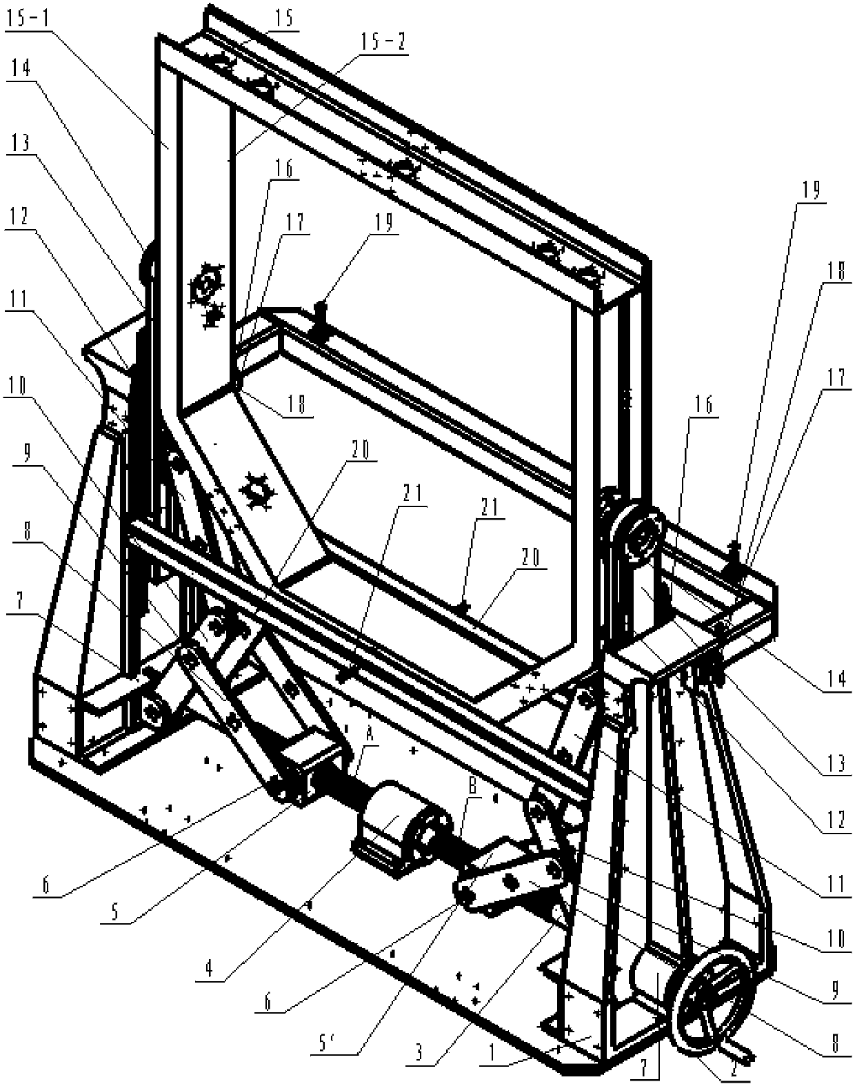
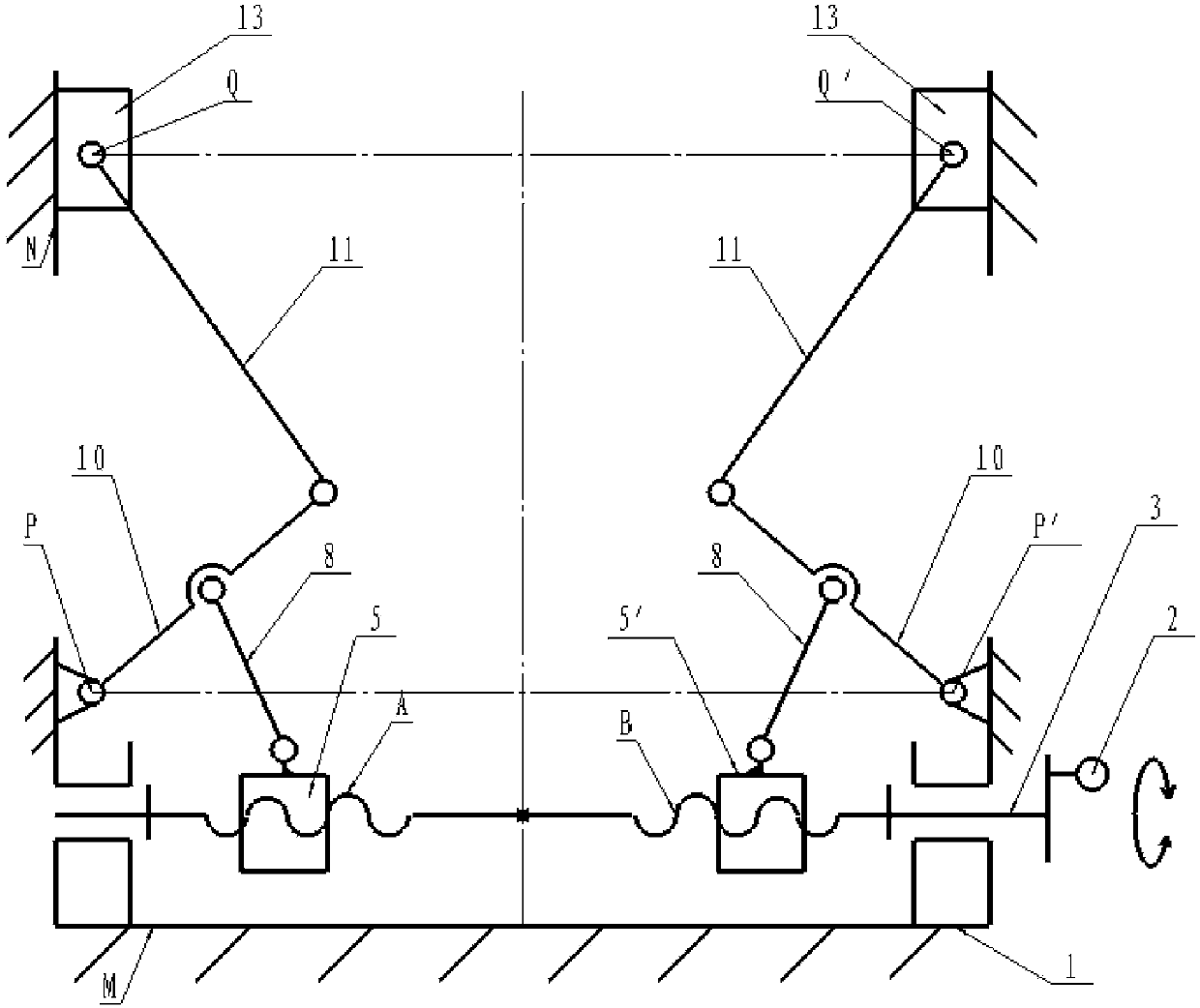
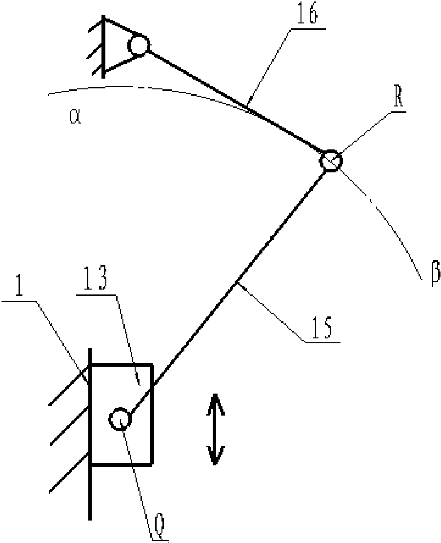
[0038] like Figure 1-Figure 5 It shows the connecting rod lifting and turning device of the present invention, which is characterized in that it includes a support frame 1, a feed hand wheel 2, a differential screw 3, a screw shaft seat 4, a left drive nut 5, a right drive nut 5', a method Blue pin shaft 6, bearing assembly 7, ejector rod 8, cylindrical positioning pin 9, rocker 10, connecting rod 11, lifting sliding guide rail 12, slider 13, shaft assembly 14, turning frame 15, turning connecting rod 16, fixing pin Shaft 17, pin clamping plate 18, limit block 19, pitch adjustment strut 20, adjustment screw rod 21, wherein:

[0039] The screw shaft seat 4 and the two left and right bearing assemblies 7 are all fixed on ...


PUM


Abstract

The invention relates to a connecting rod lifting and overturning device based on differential screw transmission and rocker slider transmission. The device is characterized in that the center of a differential screw penetrates through a lead screw axle base, two ends of the differential screw are matched and assembled with a left bearing assembly and a right bearing assembly, and a left thread section and a right thread section of the differential screw are screwed into a left drive nut and a right drive nut respectively to form a differential screw mechanism; upper table-boards of lifting slide guide rails and lower table-boards of sliders are matched and assembled; shaft assemblies are connected with the sliders and an overturning frame, one end of each overturning connecting rod is fixed with the overturning frame, and the other end is fixed or separated from with support frames through fixing pin shafts and pin clamp plates; connecting rods, the sliders and the support frames constitute a rocker slider mechanism I, and rockers swing to drive the sliders to move up and down along the lifting slide guide rails; the sliders, the overturning frame, the overturning connecting rods and the support frames constitute a rocker slider mechanism II, and the sliders linearly move up and down to drive the overturning frame to perform overturning movement. The connecting rod lifting and overturning device based on differential screw transmission and rocker slider transmission has lifting and overturning functions simultaneously, is more compact in structure, convenient to operate and good in stability, and saves confined space.

Description

technical field [0001] The invention belongs to the field of precision machinery, and in particular relates to a connecting rod lifting and turning device based on differential screw transmission and rocker slider transmission. Background technique [0002] At present, most of the lifting and turning devices realize the lifting and turning functions through different mechanical structures, that is, each function needs to be given an active force, so there are problems such as complex structure, poor stability, slow lifting speed, inconvenient operation, and high manufacturing cost. However, in a limited space, there is no report on a device that uses the differential principle and the planar four-bar principle to integrate the two functions of lifting and turning, and is stable and self-locking in place. Contents of the invention [0003] In order to solve the problems of the prior art, the purpose of the present invention is to find a device that can quickly lift and turn...

Claims


Application Information

Patent Timeline
Patent Type & Authority Applications(China)
IPC IPC(8): B66F13/00
Inventor 林昭珩谭毅任戈吴时彬杨伟
Owner INST OF OPTICS & ELECTRONICS - CHINESE ACAD OF SCI
Why Eureka
Try Eureka