A constant pressure control device and control method for a hydraulic pump

A technology of constant pressure control and hydraulic pumps, which is applied in the direction of fluid pressure actuators, servo motors, servo motor components, etc., and can solve the problem of reduced pump displacement, slow response speed of the pilot variable control system, and restrictions by fixed damping, etc. question

Active Publication Date: 2016-06-29
ZHEJIANG DETAI ELECTROMECHANICAL ENG
View PDF10 Cites 0 Cited by
  • Summary
  • Abstract
  • Description
  • Claims
  • Application Information

AI Technical Summary

Problems solved by technology

This scheme can achieve hydraulic system overload protection through reasonable hydraulic resistance matching, but there are two deficiencies: first, when the hydraulic pump is in the overload protection state, due to the existence of fixed liquid resistance, part of the pilot control hydraulic oil leaks through the fixed liquid resistance To the oil tank, the piston cavity of the variable piston is not fully acted on to reduce the pump displacement to curb the increase of system pressure. Therefore, the response speed of the hydraulic pump to the overload of the hydraulic system is weakened by the fixed hydraulic resistance; secondly, the damping from the pilot control system From the point of view, in the traditional C-type pilot hydraulic half-bridge control mode, the stability and quickness of the pilot variable control system of the hydraulic pump are restricted by the fixed damping, that is, when the fixed damping is increased, the stability of the constant pressure regulation process increases, and the constant pressure adjustment process increases. The pressure adjustment process is stable, but the response speed of the pilot variable control system of the hydraulic pump becomes slower, and the constant pressure adjustment process takes longer, thus causing damage to the hydraulic pump itself and system components, and reducing the fixed damping, the effect is opposite
It can be seen from the above that there is room for optimization and improvement in the traditional constant pressure control method of this pump

Method used


Image

  • A constant pressure control device and control method for a hydraulic pump

Examples


Embodiment Construction

[0018] Below in conjunction with accompanying drawing and embodiment the present invention will be described in further detail:

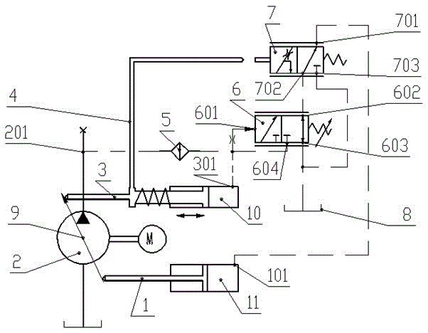
[0019] Such as figure 1 As shown, the constant pressure control device for the hydraulic pump 2 of the present invention includes a feedback rod 4, a fine filter 5, a constant pressure control valve 6 and a damping valve 7, wherein the fine filter 5 plays the role of filtering the pilot hydraulic oil. The oil inlet port of the fine filter 5 is connected with the oil discharge port 201 of the hydraulic pump 2, and the oil outlet port of the fine filter 5 is connected with the P port 604 of the constant pressure control valve and the rodless cavity 10 of the small variable piston of the hydraulic pump 2 at the same time. The A port 602 of the constant pressure control valve communicates with the P port 702 of the damping valve, and the T port 603 of the constant pressure control valve communicates with the T port 703 of the damping valve and the exter...


PUM


Abstract

The invention discloses a constant pressure control device and a control method for a hydraulic pump. Among them, the oil inlet of the fine filter is connected with the oil discharge port of the hydraulic pump, the oil outlet of the fine filter is connected with the P port of the constant pressure control valve and the rodless chamber of the small variable piston at the same time, and the A port of the constant pressure control valve is connected with the damping valve The P port is connected, the T port of the constant pressure control valve is connected with the T port of the shock absorber valve and the oil tank at the same time, the control port of the constant pressure control valve is connected with the P port of the constant pressure control valve through its internal fixed damping, and the A port of the shock absorber valve is connected with the large variable piston The rodless chamber is connected; the feedback rod is fixedly connected with the small variable piston, so that when the pressure at the oil discharge port of the hydraulic pump is higher than the proportional spring setting pressure of the constant pressure control valve, the feedback rod can move to the shock absorber driven by the small variable piston. The valve spool contacts and pushes the spool to move to the position where P port and T port of the damping valve are connected; when the pressure at the oil discharge port of the hydraulic pump is lower than the proportional spring setting pressure of the constant pressure control valve, the feedback rod can be connected with The damping valve spool is separated.

Description

technical field [0001] The invention relates to a hydraulic pump constant pressure control device and a control method, belonging to the technical field of hydraulic control. Background technique [0002] The hydraulic pump is the core component of the hydraulic system, and its performance directly affects the overall performance of the hydraulic system. With the development of hydraulic technology, the working pressure of the hydraulic system is getting higher and higher, and the output flow is getting bigger and bigger. Therefore, more stringent requirements are put forward for the response speed and stability of the hydraulic pump when the system is overloaded. In order to reduce the pressure overload damage of the hydraulic pump and hydraulic system components when the hydraulic pump is applied to the system overload, the constant pressure control method is often used to protect the hydraulic pump from overload. [0003] The traditional constant pressure control method ...

Claims


Application Information

Patent Timeline
Patent Type & Authority Patents(China)
IPC IPC(8): F15B11/00F15B13/02
Inventor 魏然方向赖振宇朱高松王贵成
Owner ZHEJIANG DETAI ELECTROMECHANICAL ENG
Why Eureka
Try Eureka