
A high voltage electrostatic discharge tube

A technology of high-voltage electrostatic and discharge tubes, applied in the direction of electrostatic and electromagnetic control tubes, single discharge channel tubes, magnetrons, etc., can solve the problem of difficult precise voltage control

Active Publication Date: 2016-10-05
青岛科远电气工程有限公司
View PDF5 Cites 0 Cited by
  • Summary
  • Abstract
  • Description
  • Claims
  • Application Information

AI Technical Summary

Problems solved by technology

[0002] Precise control of voltage in high voltage electrostatic applications is difficult

Method used


Image

  • A high voltage electrostatic discharge tube
  • A high voltage electrostatic discharge tube
  • A high voltage electrostatic discharge tube

Examples


Embodiment Construction

[0022] Embodiments of the present invention will be described below in conjunction with implementation examples:

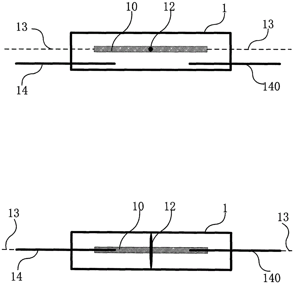
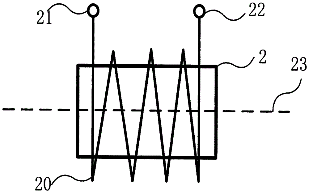
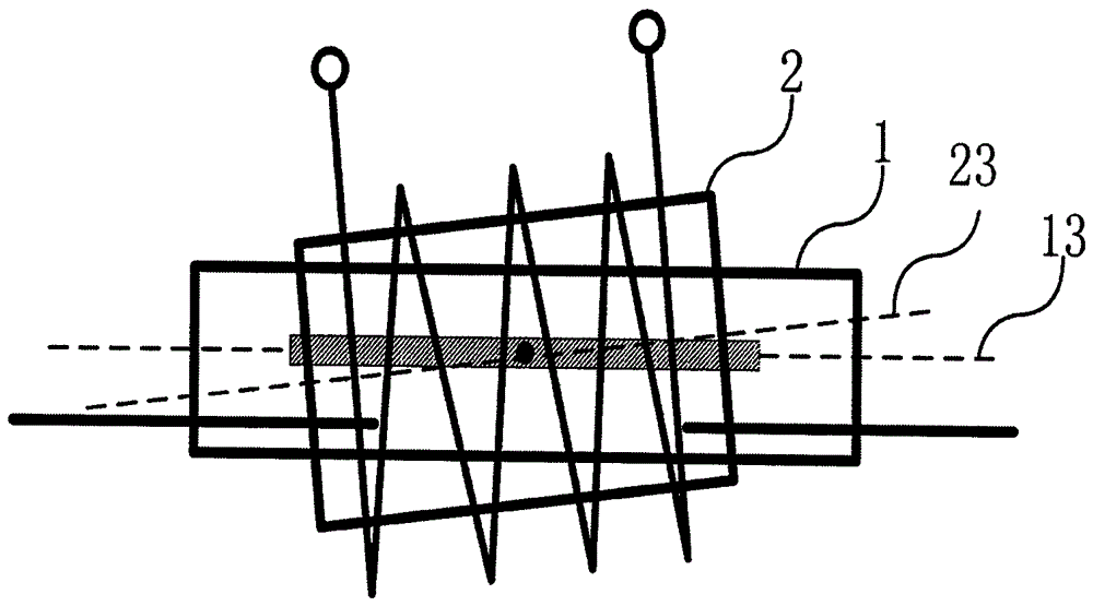
[0023] Such as figure 1 , figure 2 and image 3 As shown, this implementation example is made up of a vacuum glass tube 1, a conductive and magnetic torsion beam 10, a solenoid 2, and two main conductors 14, 140; the conductive and magnetic torsion beam 10 is an equal-arm lever; Located inside the vacuum glass tube 1, the torsion shaft 12 of the conductive and magnetic torsion beam 10 forms a rotational connection with the vacuum glass tube 1, and the axis of the torsion shaft 12 is perpendicular to the axis 13 of the vacuum glass tube 1: the solenoid 2 is set in the vacuum glass tube 1 Externally, the solenoid 2 covers the conductive and magnetic torsion beam 10, the axis 23 of the solenoid 2 is coplanar with the axis of the torsion shaft 12 of the conductive and magnetic torsion beam 10, and the axis 23 of the solenoid 2 is parallel to the vacuum glass tube ...


PUM


Abstract

The invention discloses a high-voltage electrostatic discharge tube, which is characterized in that it is composed of a vacuum glass tube, a conductive and magnetically conductive torsion beam, a solenoid, and two main conductors. The invention can be used for precise control of static voltage of high-voltage electrostatic application equipment.

Description

technical field [0001] The invention belongs to the field of high-voltage electrostatics, and in particular relates to a high-voltage electrostatic discharge tube. Background technique [0002] Precise control of voltage in high voltage electrostatic applications is difficult. If there is a discharge tube whose discharge speed can be controlled in real time, combined with a non-contact high-voltage electrostatic voltage measuring instrument to discharge slowly when the voltage exceeds a predetermined value, precise control of the voltage can be realized. Contents of the invention [0003] The object of the present invention is to propose a high-voltage electrostatic discharge tube to solve the deficiencies of the prior art. [0004] The present invention has technical content: [0005] Technical content 1: A high-voltage electrostatic discharge tube, characterized in that: it is composed of a vacuum glass tube, a conductive and magnetically conductive torsion beam, a sol...

Claims


Application Information

Patent Timeline
Patent Type & Authority Patents(China)
IPC IPC(8): H01J21/18
Inventor 俞权锋
Owner 青岛科远电气工程有限公司
Learn More