Eureka AIR delivers breakthrough ideas for toughest innovation challenges, trusted by R&D personnel around the world.

A movement structure of an imitation fire electronic candle

A technology for electronic candles and simulated fire, applied in electric light sources, electric light sources, electric light circuit layout, etc., can solve the problems of high cost, low price of electronic candles, unfavorable production, etc.

Inactive Publication Date: 2017-01-18
边海林
View PDF7 Cites 0 Cited by
  • Summary
  • Abstract
  • Description
  • Claims
  • Application Information

AI Technical Summary

Problems solved by technology

At present, the authenticity of the flame can be realistic. People shake and swing the swing blades through the technology of West Levitation. However, because the magnetism of the magnet cannot be maintained for a long time, the cost of using a magnet with a long magnetic retention time is relatively high. Later, people replaced the magnet by the principle of electromagnetism, but because the principle structure of electromagnetism is more complicated, the cost is higher than that of the original magnet to magnet, and the price of electronic candles in the market is very low, which makes the factory profit reach Negative value, not conducive to production

Method used


Image

  • A movement structure of an imitation fire electronic candle
  • A movement structure of an imitation fire electronic candle
  • A movement structure of an imitation fire electronic candle

Examples


Embodiment 1

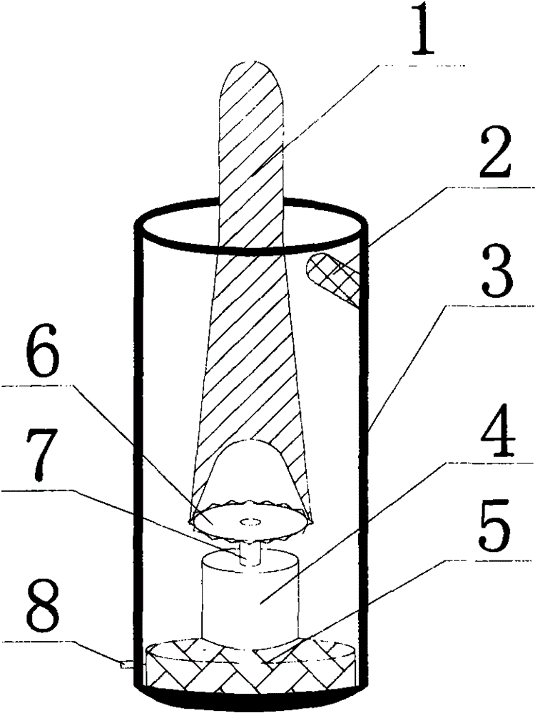
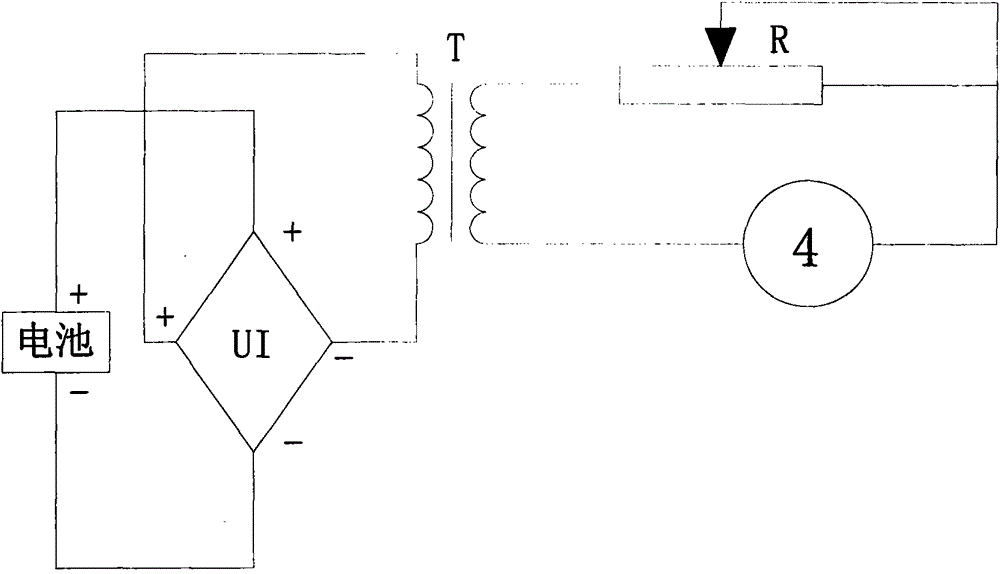
[0018] Example one: such as figure 1 with figure 2 As shown, the electronic candle in the present invention includes a candle cylinder 3, a movement, an LED lamp 2 and a swing blade 1. The movement is installed in the candle cylinder 3, the swing blade 1 is installed in the candle cylinder 3, and one end is connected to the movement. The oscillating blade 1 can be oscillated by the movement, the LED lamp 2 is installed on the top of one side of the candle cylinder 3, and the light emission direction of the LED lamp 2 intersects the oscillating blade 1, so that the light of the LED lamp 2 is projected on the swing blade 1. On the surface, the movement includes a drive unit, an electric motor 4, a current control circuit board and a battery box 5. The battery box 5 is installed at the bottom of the candle tube 3, the electric motor 4 is installed on the battery box 5, and the current control circuit board is installed on the battery box. 5, and its input end is connected with the...

Embodiment 2

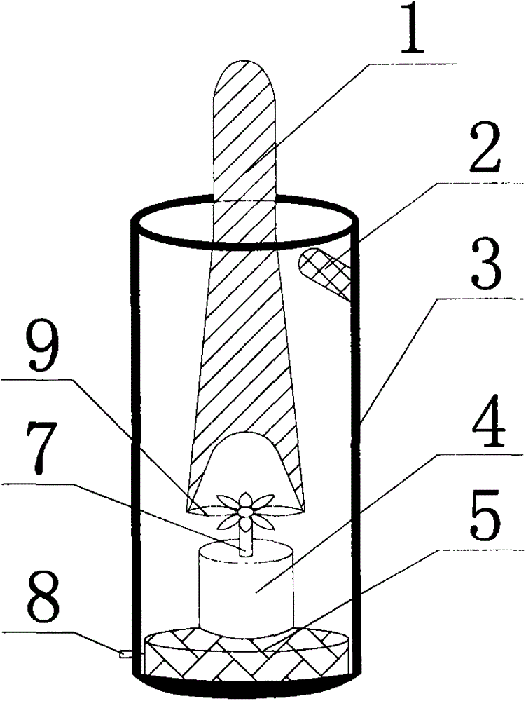
[0020] Embodiment two: such as image 3 As shown, the driving member is a fan blade 9. The center hole of the fan blade 9 is mounted on the shaft 7 of the electric motor 4. The swing blade 1 is located at one end of the electric motor 4 and has a groove, which is shaped like a "Y". The thickness on both sides is adapted to the width of the sawtooth of the fan blade 9, and the electric motor 4 drives the fan blade 9 to rotate, so that the swing blade 1 swings.

Embodiment 3

[0021] Example three: such as Figure 4 As shown, the driving member is a fan blade 9. The swing blade 1 is provided with a force receiving member 10 at one end close to the electric motor 4. The force receiving member 10 is a "petal" structure, and it is arranged on the upper part of the fan blade 9 through the fan blade 9 generates airflow, blowing the swinging blade 1 so that the swinging blade 1 swings or shakes.


PUM


Abstract

The invention provides a machine core structure of a fire simulation electronic candle. A machine core comprises a driving part, an electro-motor, a current control circuit board and a battery box. The battery box is installed at the bottom of a candle cylinder, the electro-motor is installed on the battery box, and the current control circuit board is installed in the battery box. The input end of the current control circuit board is connected with a battery in the battery box, and the output end of the current control circuit board is connected with the electro-motor. A rotating shaft of the electro-motor is installed in a center hole of the driving part. The end, located on the electro-motor, of a swing blade is provided with a groove, and then a Y shape is formed. According to the machine core structure, due to the fact that the electro-motor is provided with a gear, the gear rotates to drive the swing blade to shake or swing, and the current of the electro-motor is changed through a slide rheostat, the rotating speed of the electro-motor and the swing speed of the swing blade can be adjusted; compared with a machine core manufactured based on the electroproduction magnetism principle, the machine core structure is more stable; cost is reduced, and the structure is simplified.

Description

Technical field [0001] The invention relates to a core of an electronic candle, in particular to a core structure of a simulated fire electronic candle. Background technique [0002] At present, in daily life, various electronic light emitting devices are widely used in toys, furniture decoration articles, and gifts. At this stage, because the production of electronic candles has replaced real candles, and in order to replace real candles with electronic candles, the authenticity of its flame has become the object of research. At present, the authenticity of the flame can be lifelike. People use the west levitation technology to shake and swing the swinging blades. However, because the magnetism of the magnet cannot be maintained for a long time, the cost of using a magnet with a longer magnetic retention time is higher. Later, people replaced magnets with the principle of electromagnetism, but because the principle and structure of electromagnetism are more complicated, the cos...

Claims


Application Information

Patent Timeline
Patent Type & Authority Patents(China)
IPC IPC(8): F21S10/04F21V14/00H05B37/02F21Y115/10
Inventor 边海林曾丽丽
Owner 边海林
Why Eureka
Eureka Blog
Learn More