Machine core structure of fire simulation electronic candle
A technology for electronic candles and simulated fires, which can be applied to electric light sources, electric light sources, and electric light circuit layout, etc., and can solve problems such as high cost, complexity, and unfavorable production.
- Summary
- Abstract
- Description
- Claims
- Application Information
AI Technical Summary
Problems solved by technology
Method used
Image
Examples
Embodiment 1
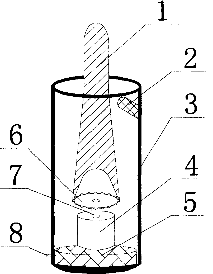
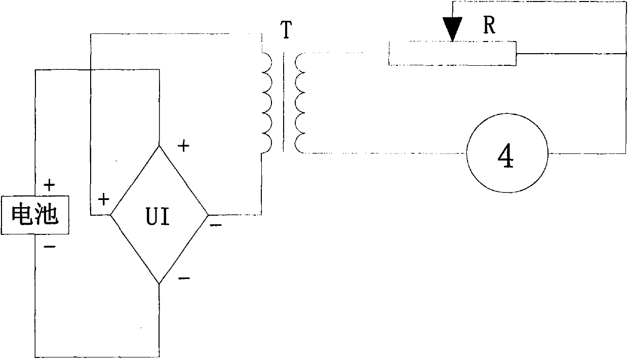
[0018] Embodiment one: if figure 1 and figure 2 As shown, the electronic candle in the present invention includes a candle cylinder 3, a movement, an LED lamp 2 and a swing blade 1, the movement is installed in the candle cylinder 3, the swing blade 1 is installed in the candle cylinder 3, and one end thereof is connected to the movement. The swing blade 1 can be swung by the movement, the LED lamp 2 is installed on the top of one side of the candle tube 3, and the light emission direction of the LED lamp 2 intersects with the swing blade 1, so that the light of the LED lamp 2 is projected on the side of the swing blade 1. On the surface, the movement includes a driving part, an electric motor 4, a current control circuit board and a battery box 5, the battery box 5 is installed on the bottom of the candle cylinder 3, the electric motor 4 is installed on the battery box 5, and the current control circuit board is installed on the battery box 5, and its input end is connected...
Embodiment 2
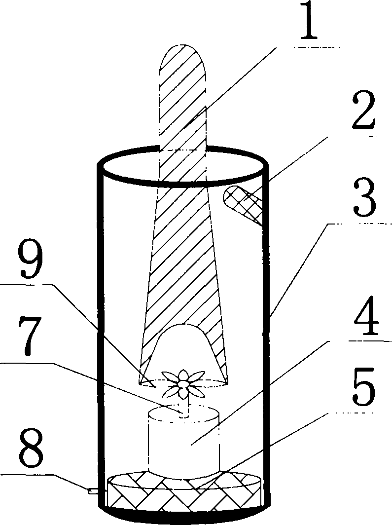
[0020] Embodiment two: if image 3 As shown, the driving part is a fan blade 9, the central hole of the fan blade 9 is installed on the rotating shaft 7 of the electric motor 4, and the swing blade 1 is located at one end of the electric motor 4 and has a groove in a "Y" shape. The thickness of both sides matches the sawtooth width of the fan blade 9, and the fan blade 9 is driven to rotate by the electric motor 4, so that the swing blade 1 swings.
Embodiment 3
[0021] Embodiment three: as Figure 4 As shown, the driving part is a fan blade 9, and the end of the swing blade 1 close to the electric motor 4 is provided with a force-bearing member 10. The force-receiving member 10 is a "petal"-shaped structure, and it is arranged on the upper part of the fan blade 9. Through the fan blade 9. Generate airflow to blow the swing blade 1, so that the swing blade 1 swings or shakes.
PUM
 Abstract
Description
Claims
Application Information
 - R&D
- Intellectual Property
- Life Sciences
- Materials
- Tech Scout
- Unparalleled Data Quality
- Higher Quality Content
- 60% Fewer Hallucinations
Browse by: Latest US Patents, China's latest patents, Technical Efficacy Thesaurus, Application Domain, Technology Topic, Popular Technical Reports.
© 2025 PatSnap. All rights reserved.Legal|Privacy policy|Modern Slavery Act Transparency Statement|Sitemap|About US| Contact US: help@patsnap.com


