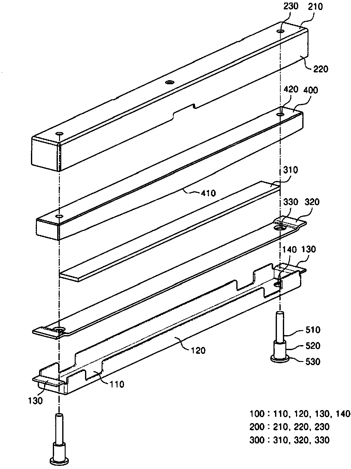
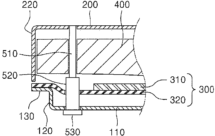
Piezoelectric vibrating device

A technology of piezoelectric vibration and vibrating plate, applied in the direction of generator/motor, circuit, piezoelectric effect/electrostrictive or magnetostrictive motor, etc., can solve the problem of loss of function

Active Publication Date: 2014-12-03
INNOCHIPS TECH
View PDF6 Cites 1 Cited by
  • Summary
  • Abstract
  • Description
  • Claims
  • Application Information

AI Technical Summary

Problems solved by technology

As described above, when the piezoelectric vibration member is damaged, the piezoelect

Method used


Image

  • Piezoelectric vibrating device
  • Piezoelectric vibrating device
  • Piezoelectric vibrating device

Examples


Embodiment Construction

[0043] In order to further explain the technical means and effects of the present invention to achieve the intended purpose of the invention, the specific implementation, structure, characteristics and Its effect is described in detail below.

[0044]Hereinafter, exemplary embodiments will be described in detail with reference to the accompanying drawings. This invention may, however, be embodied in many different forms and should not be construed as limited to the embodiments set forth herein; rather, these embodiments are provided so that this disclosure will be thorough and complete, and will convey to those skilled in the art fully convey the concept of the invention. Furthermore, the present invention is limited only by the scope of the claims.

[0045] Embodiments of the present invention will be described in detail below with reference to the accompanying drawings. However, the present invention is not limited to the embodiments disclosed below, but can be embodied i...


PUM


Abstract

Provided is a piezoelectric vibrating device including a case provided with a certain space therein, a piezoelectric vibrating member provided in the case and vibrating according to an applied voltage, a weight member provided in the case and connected to a part of the piezoelectric vibrating member in a vibration direction of the piezoelectric vibrating member, and a limitation member for limiting movement of the weight member.

Description

technical field [0001] The present invention relates to a vibration device, and more particularly, to a piezoelectric vibration device used as a tactile feedback unit in electronic equipment. Background technique [0002] When pressure is applied to a piezoelectric material, a voltage appears, which is the piezoelectric effect. When a voltage is applied to a piezoelectric material, an increase or decrease in volume or length occurs due to a change in pressure in the piezoelectric material, which is the inverse piezoelectric effect. Piezoelectric vibration devices use the inverse piezoelectric effect, and are generally applied to various electronic devices such as mobile phones, portable multimedia players (PMP), and game consoles. [0003] A piezoelectric vibration device used in a mobile phone may be used as a tactile feedback unit that responds to a user's touch through vibration. Haptic feedback means a tactile sensation that can be sensed while touching an object throu...

Claims


Application Information

Patent Timeline
IPC IPC(8): H01L41/09H01L41/04
CPCH01L41/0533H10N30/883H10N30/2041H02N2/04H02N2/00
Inventor 朴寅吉卢泰亨朴城撤金永述崔炳烈郑铉澈崔淳东
Owner INNOCHIPS TECH
Why Eureka
Try Eureka