Flow plug for chemical flooding stratified injection

A technology of chemical flooding and choke, which is applied in the direction of production fluid, wellbore/well components, earthwork drilling and production, etc. It can solve the problems of large loss of chemical fluid viscosity, unsatisfactory chemical flooding effect, and inability to maintain chemical fluid stability.

Active Publication Date: 2014-12-10
大庆康盛石油节能科技开发有限公司
View PDF6 Cites 0 Cited by
  • Summary
  • Abstract
  • Description
  • Claims
  • Application Information

AI Technical Summary

Problems solved by technology

[0003] The purpose of the present invention is to provide a layered injection choke for chemical flooding to solve the complex structure of the prior art. While controlling the flow rate, the viscosity loss of the chemical liquid passing through the flow control device is large and cannot be maintained. The stability of chemical fluid and the effect of chemical flooding cannot meet the needs of all situations

Method used


Image

  • Flow plug for chemical flooding stratified injection
  • Flow plug for chemical flooding stratified injection
  • Flow plug for chemical flooding stratified injection

Examples


Embodiment Construction

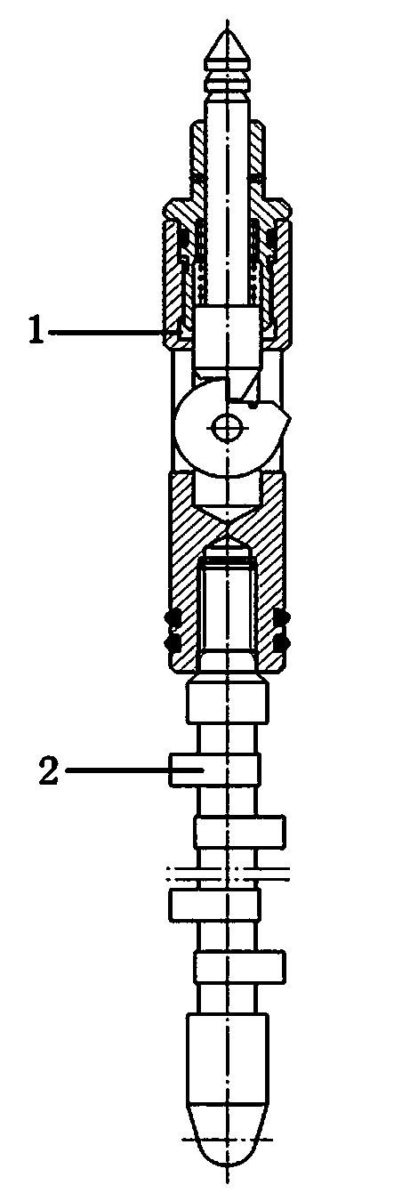
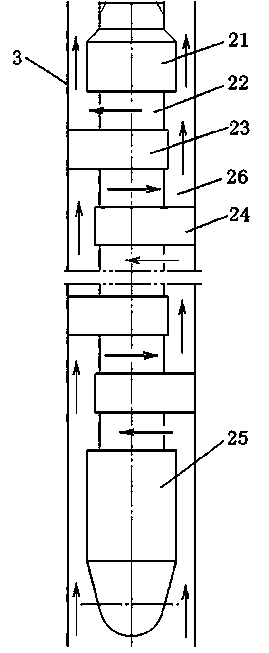
[0014] see Figure 1-7 , the present invention is a layered injection choke for chemical flooding, which is composed of an upper joint 1 and a choke core 2, wherein the upper joint 1 and the choke core 2 are screwed together and installed in a chemical flooding injection device (existing Technology) in the offset hole 3, cooperate with the smooth inner surface of the offset hole 3 to form a labyrinth flow channel 26.

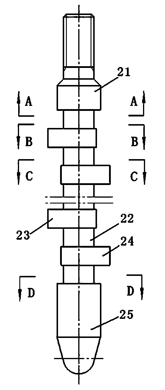
[0015] The choke core 2 is composed of an inlet end 25, a center column 22, a left stopper 23, a right stopper 24 and an outlet end 21 arranged on the same axis, and the top and bottom ends of the center column 22 are respectively connected with cross-sectional shapes Outlet port 21 and inlet port 25 are waist-shaped. A plurality of left stoppers 23 and right stoppers 24 are equidistantly connected to the central column 22 between the inlet end 25 and the outlet end 21 . The left block 23 and the right block 24 are in the shape of a circular plate with a small...


PUM


Abstract

A flow plug for chemical flooding stratified injection is composed of an upper connector (1) and a flow plugging core (2), wherein the upper connector (1) and the flow plugging core (2) are connected in a threaded mode and then arranged in an eccentric hole of a chemical flooding stratified injection device. The flow plug is characterized in that the flow plugging core (2) is matched with the inner smooth surface of the eccentric hole to form a labyrinth flow passage (26). By means of the action of the labyrinth flow passage, a flow field of liquid flow is distributed repeatedly for multiple times to consume energy, and resistance is generated to control flow of chemical liquid. Therefore, flow is controlled, viscosity loss of the chemical liquid passing through a flow control device is small, and stability of the chemical liquid is retained. Accordingly, the flow plug serves as an important measure to improve chemical flooding effect.

Description

technical field [0001] The invention relates to an oil recovery process device in an oil field, in particular to a layered injection choke for chemical flooding. Background technique [0002] At present, the application of chemical flooding and separate injection technology in oil fields is becoming more and more common, and the applied well conditions are becoming more and more complex. The traditional chemical flooding choke has a complicated structure. The viscosity loss of the chemical fluid is large, the stability of the chemical fluid cannot be maintained, and the chemical flooding effect cannot meet the needs of all situations. Contents of the invention [0003] The purpose of the present invention is to provide a layered injection choke for chemical flooding to solve the complex structure of the prior art. While controlling the flow rate, the viscosity loss of the chemical liquid passing through the flow control device is large and cannot be maintained. The stabil...

Claims


Application Information

Patent Timeline
Patent Type & Authority Applications(China)
IPC IPC(8): E21B43/00
Inventor 康庆刚
Owner 大庆康盛石油节能科技开发有限公司
Why Eureka
Try Eureka