Serially-connected composite throttling speed regulating loop for lifter

A throttling speed regulation, compound technology, applied in mechanical equipment, fluid pressure actuating devices, servo motors, etc., can solve the problems of low speed stability, poor speed rigidity, etc., to achieve good speed stability, small impact, Well-designed effects

Inactive Publication Date: 2014-12-10
芜湖高昌液压机电技术有限公司
View PDF6 Cites 6 Cited by
  • Summary
  • Abstract
  • Description
  • Claims
  • Application Information

AI Technical Summary

Problems solved by technology

[0003] Aiming at the problem of low speed stability caused by the poor speed rigidity of the speed regulating circuit of the existing lift, the present invention provides a series compound throttling speed regulating circuit of the lift, by setting throttle valves at the inlet and outlet respectively , to achieve the purpose of increasing the speed rigidity

Method used


Image

  • Serially-connected composite throttling speed regulating loop for lifter

Examples


Embodiment 1

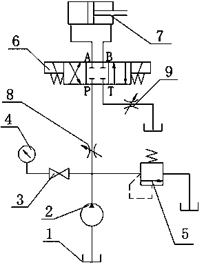
[0016] Such as figure 1 As shown, the series compound throttling speed regulating circuit of the lift includes oil tank 1, hydraulic pump 2, stop valve 3, pressure gauge 4, overflow valve 5, reversing valve 6, hydraulic cylinder 7, throttle valve A8, throttle The flow valve B9, the inlet oil pipe of the hydraulic pump 2 is connected with the oil tank 1, the outlet oil pipe is connected with the cut-off valve 3, the overflow valve 5 and the throttle valve A8 respectively, and the other end of the cut-off valve 3 is connected with the pressure gauge 4 The oil return pipe of the overflow valve 5 is connected to the oil tank 1, the other end of the throttle valve A8 is connected to the oil inlet P of the reversing valve 6, and the hydraulic cylinder 7 is connected to the reversing valve 6 Above, the throttle valve B9 is connected in series on the oil return line of the reversing valve 6 .

[0017] The reversing valve 6 is a three-position, four-way electromagnetic reversing valve...


PUM


Abstract

The invention discloses a serially-connected composite throttling speed regulating loop for a lifter and belongs to the field of hydraulic transmission. The serially-connected composite throttling speed regulating loop comprises an oil tank, a hydraulic pump, a stop valve, a pressure gauge, an overflow valve, a reversing valve, a hydraulic cylinder, a throttling valve A and a throttling valve B. The inlet oil pipe of the hydraulic pump is connected with the oil tank. The outlet pipe of the hydraulic pump is respectively connected with the stop valve, the overflow valve and the throttling valve A. The hydraulic cylinder is connected to the reversing valve. The oil return pipeline of the reversing valve is serially connected with the throttling valve B. The serially-connected composite throttling speed regulating loop is simple in structure, reasonable in design and easy to manufacture, and the problem that an existing lifter is low in speed stability due to the fact that the speed regulating loop of the lifter is poor in speed rigidity is solved.

Description

technical field [0001] The invention belongs to the field of hydraulic transmission, and more specifically relates to a speed regulating circuit for lifting and lowering a lift. Background technique [0002] With the continuous development of the automobile industry, automobile repair and maintenance has gradually become a new industry. Among them, the lift, as an important tool in the process of car repair and maintenance, has also developed rapidly. The lift is mainly to raise the car from a safe height to another safe height, so as to facilitate manual operation and maintenance. At present, there are many types of lifts, which can be divided into mechanical transmission and hydraulic transmission according to the transmission mode. The mechanical transmission structure is simple and the price is cheap, but the lifting weight is limited, and the lead screw or working nut is prone to slipping, which poses a great safety hazard. The hydraulic transmission lift has good sa...

Claims


Application Information

Patent Timeline
Patent Type & Authority Applications(China)
IPC IPC(8): F15B11/04
Inventor 高昌六
Owner 芜湖高昌液压机电技术有限公司
Why Eureka
Try Eureka