Liquid supply equipment, control method of liquid supply equipment, hydraulic system and safety valve detection system

A safety valve and liquid supply technology, applied in the hydraulic field, can solve problems such as output flow fluctuation, poor micro-flow stability, and low applicable pressure, and achieve the effects of high speed regulation performance, high speed rigidity, and good speed transmission performance

Pending Publication Date: 2020-12-29
CCTEG CHINA COAL RES INST
View PDF0 Cites 0 Cited by
  • Summary
  • Abstract
  • Description
  • Claims
  • Application Information

AI Technical Summary

Problems solved by technology

[0003] However, when the speed regulating valve e regulates the liquid flow, there are problems of low applicable pressure and poor micro-flow stability, and, in the case of extremely small flow, the booster cylinder f is prone to creeping phenomenon, which makes its output flow fluctuate , causing the liquid supply equipment to fail to output high-pressure liquid with a constant flow rate

Method used


Image

  • Liquid supply equipment, control method of liquid supply equipment, hydraulic system and safety valve detection system
  • Liquid supply equipment, control method of liquid supply equipment, hydraulic system and safety valve detection system
  • Liquid supply equipment, control method of liquid supply equipment, hydraulic system and safety valve detection system

Examples


Embodiment approach 2

[0070] The present invention provides a liquid supply method for the above liquid supply equipment. see Figure 6 and Figure 7 , the above liquid supply methods include:

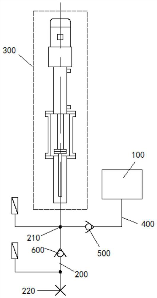
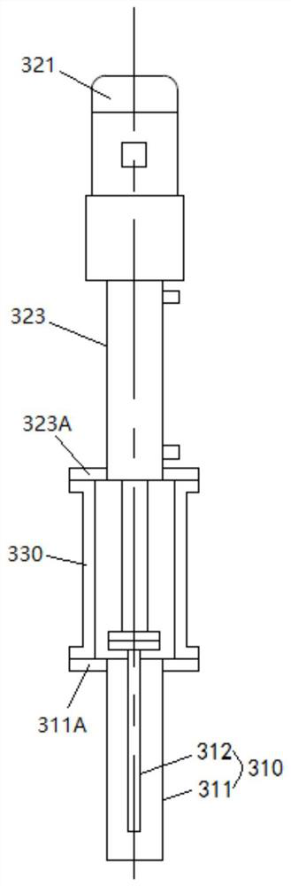
[0071] S100: Preliminary step: make the first group of loading devices 300 perform a liquid suction operation. At this time, the working fluid is stored in the working chamber of the plunger cylinder 311 in the first group of loading devices 300 .

[0072] Wherein, the liquid suction operation includes: controlling the motor 321 to rotate in a first direction, so as to move the first piston rod 312 from the first position to the second position. Wherein, when the first piston rod is at the first position, the first end of the first piston rod is flush with the bottom of the working chamber of the plunger cylinder. When the first piston rod is at the second position, the first piston rod is flush with the top of the working chamber of the plunger cylinder.

[0073] S200: first liquid supply step: make the...

Embodiment approach 3

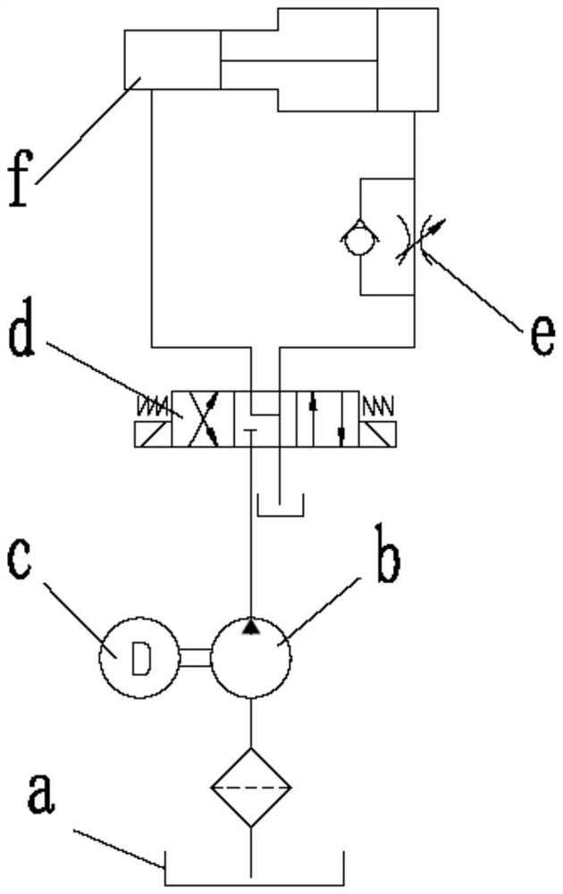
[0090] Embodiment 2 of the present invention provides a hydraulic system. see figure 2 and Figure 10 , the hydraulic system includes the above-mentioned liquid supply device A and the execution device B, and the liquid supply port 220 of the liquid supply device A communicates with the liquid inlet port of the execution device B.

[0091] At this time, the high-pressure liquid provided by the liquid supply device A can drive the actuator B to perform linear motion and reciprocating motion.

[0092] It should be noted that the structure of the above-mentioned actuator B can be selected according to the actual situation, as long as the actuator B can convert the pressure of the high-pressure liquid into the power of linear motion or reciprocating motion.

[0093] For example, the aforementioned executing device B may be a hydraulic cylinder.

[0094] Compared with the prior art, the beneficial effects of the hydraulic system provided by the embodiment of the present inventi...

Embodiment approach 4

[0096] The opening pressure of the safety valve for the hydraulic support will affect the support performance of the hydraulic support, and then affect the stability of the surrounding rock of the working face. If the opening pressure of the safety valve is too low, the working resistance of the column and the supporting jack will be insufficient, resulting in the appearance of mine pressure on the working face. If the opening pressure is too high, the column and the jack will be damaged due to the excessive working resistance and the inability to overflow and release the pressure in time.

[0097] According to the requirements of national standards, before the safety valve leaves the factory, the opening, overflow and closing characteristics of the safety valve must be randomly checked. However, during the detection process of the safety valve, under different detection flow rates and detection pressures, the measured opening pressure, overflow maximum value, overflow minimum...


PUM


Abstract

The invention discloses liquid supply equipment, a control method of the liquid supply equipment, a hydraulic system and a safety valve detection system. High-pressure liquid with constant flow can beoutput. The liquid supply equipment comprises a liquid tank, a liquid supply pipeline, a loading device, a first valve and a second valve, wherein a liquid inlet and a liquid supply port are arrangedon the liquid supply pipeline the loading device comprises a plunger cylinder and a driving device, the plunger cylinder comprises a plunger cylinder barrel and a piston in sliding fit with a workingcavity of the plunger cylinder barrel, a first piston rod is connected to the piston, the liquid tank communicates with a working cavity of the plunger cylinder barrel through a liquid inlet pipeline, a liquid inlet of the liquid supply pipeline communicates with the working cavity of the plunger cylinder barrel, the driving device comprises a motor and a transmission assembly, the transmission assembly can convert rotation of the motor into reciprocating motion of the first piston rod, transmission parts in the transmission assembly are made of rigid materials, the first valve is connected to the liquid inlet pipeline in series, and the second valve is connected to the liquid supply pipeline in series.

Description

technical field [0001] The invention relates to the field of hydraulic technology, in particular to a liquid supply equipment and its control method, a hydraulic system and a safety valve detection system. Background technique [0002] The hydraulic system is a device that uses liquid as the working medium and uses the pressure of the liquid to achieve power output. In the prior art, it is necessary to provide liquid with pressure over 60MPa to the emulsion system, and the flow rate can be adjusted, see figure 1 , its liquid supply equipment generally includes liquid tank a, liquid pump b, motor c, reversing valve d, speed control valve e and booster cylinder f. The motor c drives the liquid pump b to provide hydraulic power, and the liquid flows into the speed regulating valve e through the reversing valve d, and then enters the low-pressure side of the booster cylinder f after the flow is adjusted by the speed regulating valve e, pushing the piston of the booster cylinder...

Claims


Application Information

Patent Timeline
Patent Type & Authority Applications(China)
IPC IPC(8): F04B17/03F04B23/06F04B49/06F04B53/10F04B53/16F15B21/041F15B21/0423F16K17/00
CPCF04B17/03F04B23/06F04B49/06F04B53/10F04B53/16F15B21/041F15B2211/20515F15B2211/20546F15B2211/20576F15B2211/255F16K17/00F15B21/0423
Inventor 牛一村刘欣科赵忠辉沙宝银王阳阳刘金国崔述凯杨建新杨金祥孙红波姚玉维
Owner CCTEG CHINA COAL RES INST
Why Eureka
Try Eureka