Position sensing system of intelligent vehicle navigation

A relationship and sensor technology, applied to vehicle components, road network navigators, steering controls installed on vehicles, etc., can solve problems such as inability to effectively deal with noise and interference, lack of accuracy and robustness, etc.

Inactive Publication Date: 2014-12-10
TOMORROWS TRANSPORTATION TODAY
View PDF0 Cites 22 Cited by
  • Summary
  • Abstract
  • Description
  • Claims
  • Application Information

AI Technical Summary

Problems solved by technology

In summary, this ratio-based method cannot effectively handle noise and interference, thus lacking accuracy and robustness

Method used


Image

  • Position sensing system of intelligent vehicle navigation
  • Position sensing system of intelligent vehicle navigation
  • Position sensing system of intelligent vehicle navigation

Examples


Embodiment Construction

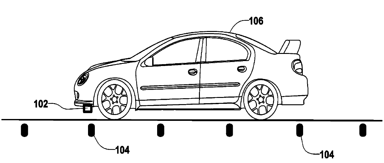
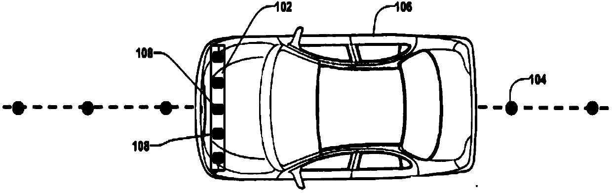
[0040] figure 1 and figure 2 A side view and a top view of an embodiment of a position detection device 102 mounted on a moving object (eg, a vehicle) 106 are shown, respectively. When the object 106 is traveling along the lane, the position detection device 102 is capable of detecting a positional deviation of the device 102 relative to the magnetic marker 104 installed in the lane. By detecting this positional deviation, the position detection device 102 can provide the lateral deviation of the moving object 106 relative to the lane.

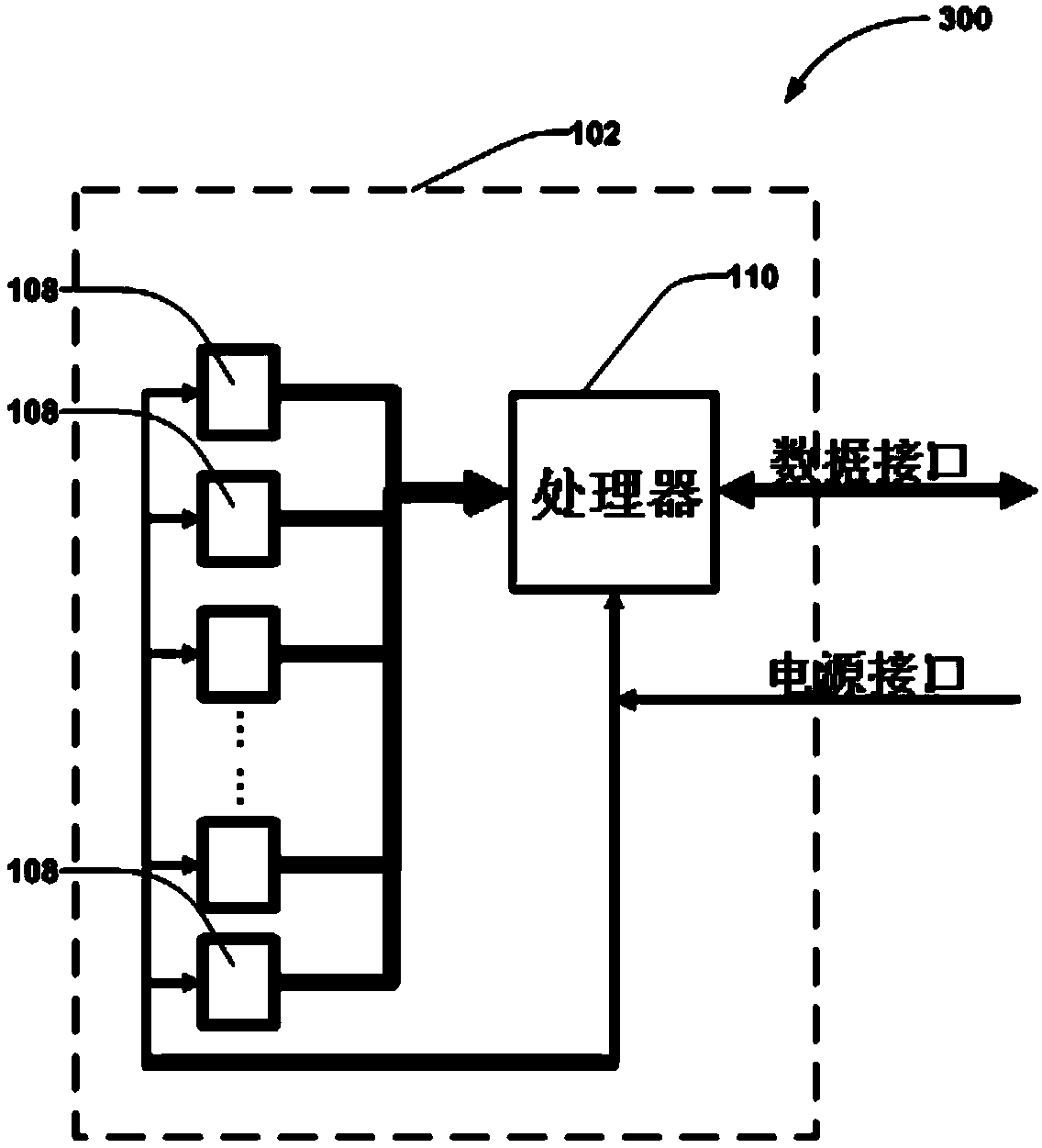
[0041] image 3 is a block diagram 300 of one embodiment of the position detection device 102 . In this embodiment, the position detection device 102 includes at least two magnetic field sensors 108 and a processor 110 . figure 1 , figure 2 ,and image 3 Five magnetic field sensors 108 are shown separately in , which is for illustrative purposes only. The magnetic field sensor 108 can be integrated in the same case or can be packaged ...


PUM


Abstract

The invention discloses a method used for determining position deviation of an object relative to a magnetic marker. At least two magnetic field sensors installed on the object are used for sensing the magnetic field of the magnetic marker. Each of the magnetic field sensors senses at least two axial magnetic field intensity components. According to the invention, measured difference values of the magnetic field intensity components in each axial direction of the magnetic field sensors are calculated, and then based on above two difference values, i.e., one difference value is provided in each of the axial directions, position deviation between the object and the magnetic marker is determined. The method can be used for providing a transverse deviation with respect to a path followed by a mobile object like a vehicle for an intelligent vehicle navigation. Thus, the intelligent vehicle navigation system determines and carries out required steering control, thereby leading the mobile object to move along the required followed path automatically.

Description

technical field [0001] The present invention relates to a position sensing method and system for determining position relative to a magnetic marker. When installed on a vehicle, the position sensing system can determine the position of the vehicle relative to the lane it is in. More specifically, magnetic markers are installed in driveways to provide a road reference. When a vehicle is traveling along such a lane, the position sensing system detects the magnetic field strength of the magnetic markers and thereby estimates the position of the vehicle relative to the lane. This location information can be used in an intelligent vehicle navigation system to automatically guide the vehicle along the lane. Background technique [0002] A robust, reliable and accurate sensing system is important for automated control of moving vehicles. For vehicle lateral control, typical sensing technologies include vision-based, global positioning system (such as DGPS), and road reference sy...

Claims


Application Information

Patent Timeline
Patent Type & Authority Applications(China)
IPC IPC(8): G01C21/26
CPCG01C21/26B62D1/28B62D15/025
Inventor 黄继华但汉曙张维斌
Owner TOMORROWS TRANSPORTATION TODAY
Why Eureka
Try Eureka