Horn radiator for Ka-band plate array antenna

An array antenna and radiator technology, applied in waveguide horns, circuits, etc., can solve the problems that the distribution is limited by the antenna form, the antenna unit is not available, and it is difficult to greatly improve it. It achieves strong practicability, uniform electromagnetic field distribution, and reduced cost. Effect

Active Publication Date: 2014-12-10
BEIJING RES INST OF TELEMETRY +1
View PDF1 Cites 10 Cited by
  • Summary
  • Abstract
  • Description
  • Claims
  • Application Information

AI Technical Summary

Problems solved by technology

[0003] Traditional antenna units used in satellite communication antenna arrays generally do not have high aperture e...

Method used


Image

  • Horn radiator for Ka-band plate array antenna

Examples


Embodiment Construction

[0022] The working principle and working process of the present invention will be further explained and illustrated below in conjunction with the accompanying drawings.

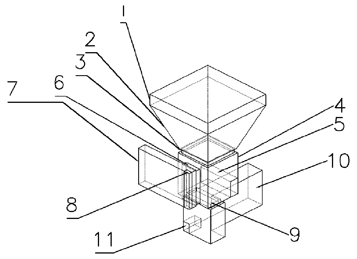
[0023] Such as figure 1 As shown, a kind of horn radiator of the present invention that is used for Ka frequency band planar array antenna comprises: horn radiator port 1, horn radiator side wall 2, horn radiator feeding port 3, waveguide orthogonal mode coupler 4, the first A tuning block 5, a square waveguide side wall feeding port 6, a side wall waveguide 7, a second tuning block 8, a square waveguide bottom surface feeding port 9, a curved waveguide 10, and a curved waveguide tuning block 11;

[0024] The horn radiator port 1 is located at the front section of the horn radiator side wall 2; one end of the horn radiator feed port 3 is connected to the rear end of the horn radiator side wall 2; the other end of the horn radiator feed port 3 is orthogonal to the waveguide One end of the mode coupler 4 is co...


PUM

PropertyMeasurementUnit
Heightaaaaaaaaaa

Abstract

The invention relates to a horn radiator for a Ka-band plate array antenna. The horn radiator for the Ka-band plate array antenna comprises a horn radiator port, a horn radiator side wall, a horn radiator feed port, a waveguide orthogonal mode coupler, a first tuning block, a square waveguide side wall feed port, a side wall waveguide, a second tuning block, a square waveguide bottom surface feed port, a bent waveguide and a bent waveguide tuning block. According to the horn radiator for the Ka-band plate array antenna, the distribution of coupled electromagnetic fields can be uniform through a horn radiator structure formed by the horn radiator port and the horn radiator side wall, so that a horn radiator of high aperture efficiency is obtained.

Description

technical field [0001] The invention relates to a horn radiator for a Ka-band flat-panel array antenna, which can be used as a front end of a static communication system and a dynamic communication system at the ground end of a Ka-band satellite communication system, and belongs to the technical field of microwave antennas. Background technique [0002] At present, satellite communication technology using Ka-band has advantages that other frequency bands do not have. For example, compared with traditional Ku-band communication satellites, the number of communication nodes that Ka-band satellites can support is much larger than that of Ku-band. Moreover, Ka-band communication satellites have 4 times the communication bandwidth of Ku-band satellites. After the communication satellites working in the Ka frequency band adopt spot beams, a single spot beam can cover an area with a radius of 250km to 1000km, provide 10 to 25 times frequency multiplexing, and support smaller termin...

Claims


Application Information

Patent Timeline
IPC IPC(8): H01Q13/02
Inventor 史永康李鹏飞陈剑刘昊
Owner BEIJING RES INST OF TELEMETRY
Why Eureka
Try Eureka