A frequency scanning CTS flat panel array antenna

An array antenna and frequency scanning technology, which is applied in the directions of antenna, antenna coupling, antenna array, etc., can solve the problems of large loss, large reflective surface structure size, and low efficiency

Inactive Publication Date: 2019-01-11
NINGBO UNIV
View PDF3 Cites 7 Cited by
  • Summary
  • Abstract
  • Description
  • Claims
  • Application Information

AI Technical Summary

Problems solved by technology

Although the SIW structure of the low-profile frequency-scanning CTS panel array antenna can reduce the thickness of the overall structure, as the array increases, the loss will increase, making it impossible to achieve high-

Method used


Image

  • A frequency scanning CTS flat panel array antenna
  • A frequency scanning CTS flat panel array antenna
  • A frequency scanning CTS flat panel array antenna

Examples


Embodiment

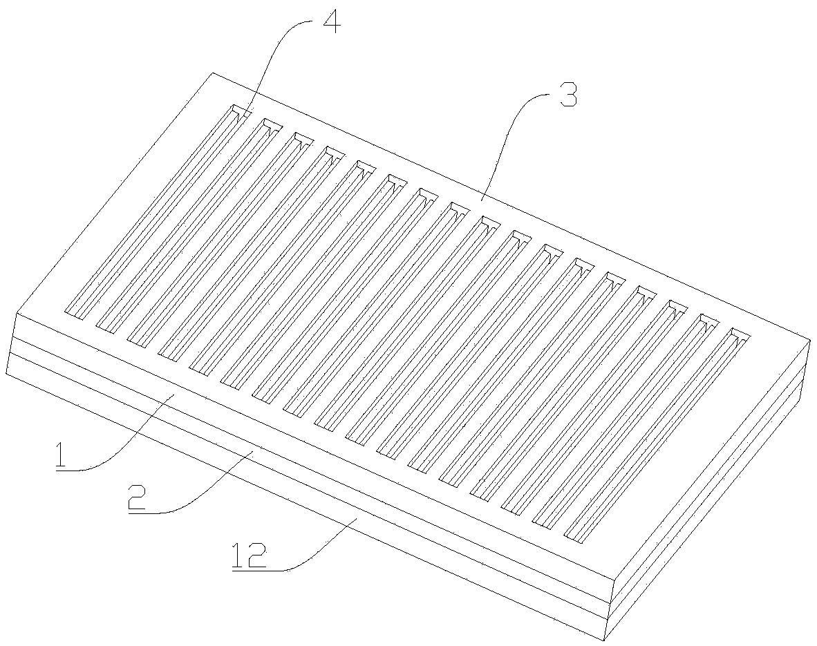
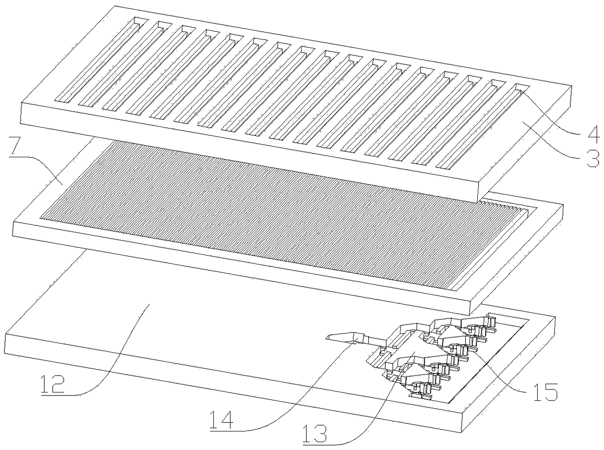
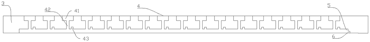
[0028] Embodiment: As shown in the figure, a frequency scanning CTS panel array antenna includes a radiation layer and a broadband line source layer arranged in sequence from top to bottom. The radiation layer includes a first radiation unit 1 and a second radiation unit 2. A radiation unit 1 is located above the second radiation unit 2; the first radiation unit 1 includes a first metal plate 3 and 17 continuous transverse branches 4 arranged on the first metal plate 3, the first metal plate 3 is a rectangular plate, 17 Continuous lateral branches 4 are evenly spaced on the first metal plate 3 from left to right, each continuous lateral branch 4 includes a first rectangular waveguide cavity 41, a second rectangular waveguide cavity 42 and a third rectangular waveguide cavity 43, the first rectangular waveguide cavity The rectangular waveguide cavity 41 is located above the second rectangular waveguide cavity 42, the front end surface of the first rectangular waveguide cavity 41...


PUM


Abstract

The invention discloses a frequency scanning CTS flat panel array antenna, includes a radiation layer and a broadband line source layer arranged in order from top to bottom, the radiation layer includes a first radiation element and a second radiation element, a first radiating element is located above the second radiating element, the first radiation unit includes a first metal plate and 17 continuous transverse branches disposed on the first metal plate, the first metal plate is a rectangular plate, 17 consecutive transverse branch are uniformly spaced from left to right on that first metalplate. The second radiating unit comprises a second metal plate on which a non-uniform slow wave structure, a sixth rectangular waveguide cavity and a seventh rectangular waveguide cavity are sequentially arranged from left to right, and a broadband line source layer comprises a third metal plate, a single ridge waveguide feeding network and a single ridge waveguide. The second radiating unit comprises a second metal plate, wherein the second metal plate is provided with a non-uniform slow wave structure, a sixth rectangular waveguide cavity and a seventh rectangular waveguide cavity from leftto right Rectangular waveguide converter and quasi-TEM mode line source generator. The invention has the advantages of small size, high gain and high efficiency.

Description

technical field [0001] The invention relates to a flat panel array antenna, in particular to a frequency scanning CTS flat panel array antenna. Background technique [0002] In recent years, millimeter-wave (MMW) antenna arrays with beam-steering capabilities are of great value and have been widely used in the fields of radar, imaging, and high-speed communication. At present, there are mainly three types of antennas used to realize high-performance antenna arrays with high beam pointing accuracy: mechanical scanning antennas, phase scanning antennas, and frequency scanning antennas. [0003] Among them, the mechanical scanning antenna realizes the beam scanning of the antenna through a mechanical scanning method, which has a slow scanning speed and has reliability problems; the phase scanning antenna uses a phase shifter to control the feeding phase of each antenna unit. Realize the beam scanning of the antenna; the frequency scanning antenna is to change the phase relatio...

Claims


Application Information

Patent Timeline
IPC IPC(8): H01Q1/36H01Q1/50H01Q1/52H01Q21/00
CPCH01Q1/36H01Q1/50H01Q1/52H01Q21/0006
Inventor 尤清春黄季甫秦丽婷尤阳方陈剑
Owner NINGBO UNIV
Why Eureka
Try Eureka