
Variable bandwidth RF filter

A filter and bandwidth technology, applied in the field of RF filters, can solve the problem of fewer filters and achieve the effect of easy change, easy bandwidth, and simple structure

Inactive Publication Date: 2014-12-10
ACE TECH
View PDF2 Cites 3 Cited by
  • Summary
  • Abstract
  • Description
  • Claims
  • Application Information

AI Technical Summary

Problems solved by technology

[0005] Therefore, tunable filters are needed, however existing research mainly focuses on filters with tunable frequency, and there are relatively few studies on filters that can change their bandwidth

Method used


Image

  • Variable bandwidth RF filter
  • Variable bandwidth RF filter
  • Variable bandwidth RF filter

Examples


Embodiment Construction

[0030] As the invention allows for various changes and embodiments, specific embodiments are shown in the drawings and described in detail in the specification. However, this does not mean that the present invention is limited to these specific implementation modes, and it should be understood that any changes, equivalents, and replacements are included in the present invention as long as they do not depart from the spirit and technical scope of the present invention. In describing the drawings, like elements have been given like numerals.

[0031] Some embodiments of the present invention will be described in more detail below with reference to the accompanying drawings.

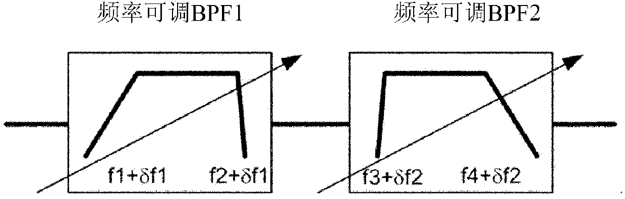
[0032] figure 1 It is a schematic structural diagram of a bandwidth-tunable filter according to an embodiment of the present invention.

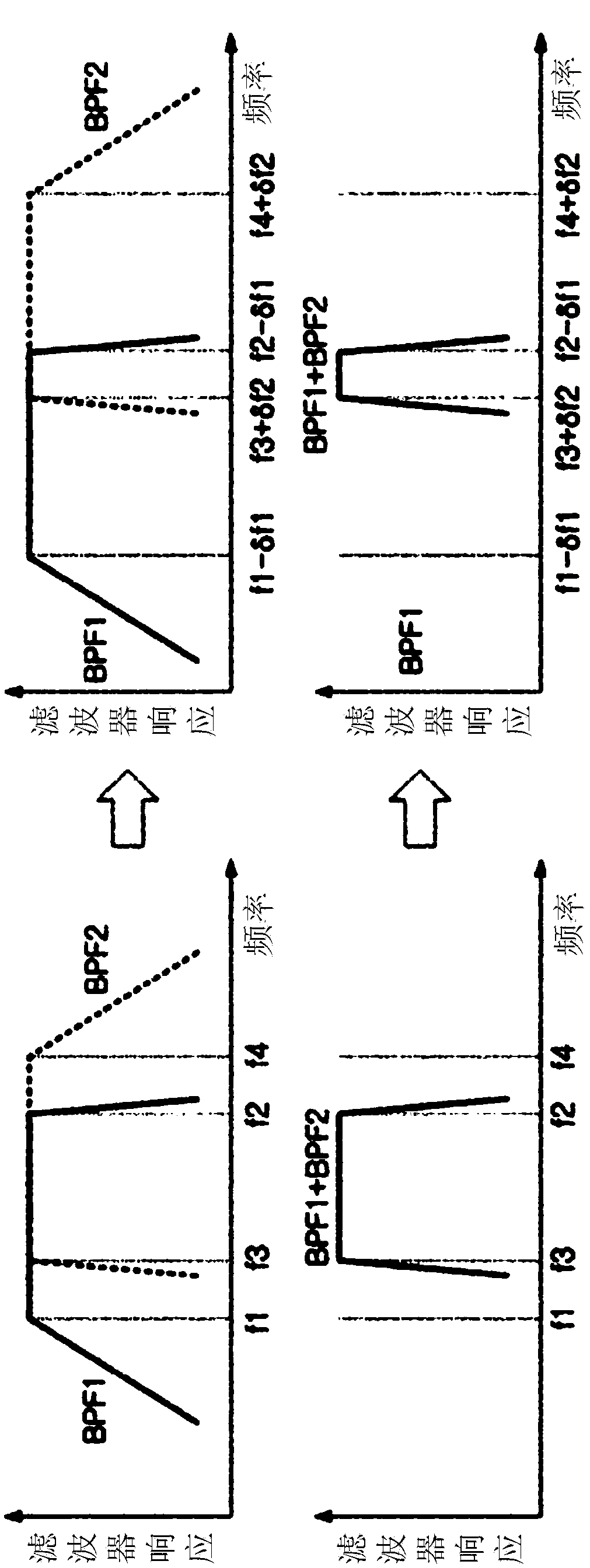
[0033] refer to figure 1 , the bandwidth-tunable filter in this embodiment of the present invention may include two frequency-tunable filters connected in cascade.

...


PUM


Abstract

Disclosed is a variable bandwidth RF filter. The disclosed filter comprises: a first filter unit having a first bandwidth and a variable-frequency structure; and a second filter unit having a second bandwidth and a variable-frequency structure. The first filter unit and the second filter unit are coupled to a cascade structure, and the bandwidth is adjusted by varying the frequency of the first filter unit and of the second filter unit. The disclosed filter is advantageous in that the variation of the bandwidth can be easily performed using a simple structure.

Description

technical field [0001] Embodiments of the present invention relate to RF filters, and more particularly to RF filters with which bandwidth can be varied. Background technique [0002] Recently, the communication system is evolving from 3G to 4G. Currently existing communication systems and advanced communication systems coexist. In this case, there have been studies focusing on how to make full use of existing base station equipment, and one of the results of these studies is the tunable filter technology. [0003] With the development of communication technology, the system bandwidth using the existing communication system is gradually decreasing, while the system bandwidth using the new communication system is gradually increasing. [0004] If an RF filter capable of changing the bandwidth and center frequency is developed, it will be possible to remotely change the bandwidth and center frequency of the filter according to the development of communication technology with...

Claims


Application Information

Patent Timeline
Patent Type & Authority Applications(China)
IPC IPC(8): H01P1/20
CPCH01P1/2084H01P1/20H01P1/2053H01P1/208H01P7/04
Inventor 千东完
Owner ACE TECH
Learn More