Object detection device
- Summary
- Abstract
- Description
- Claims
- Application Information
AI Technical Summary
Benefits of technology
Problems solved by technology
Method used
Image
Examples
first embodiment
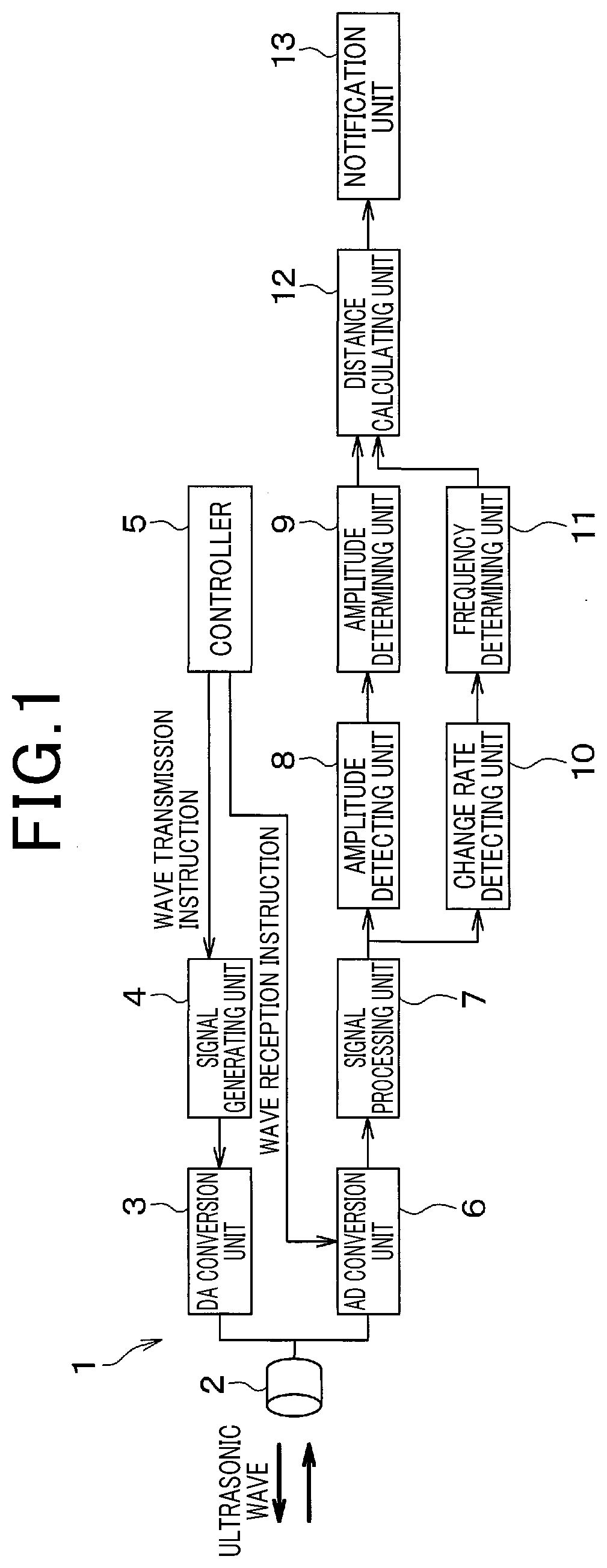
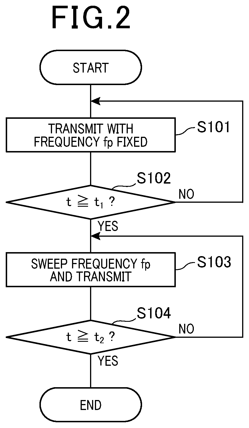
[0043]The first embodiment will be described. An object detection device according to the present embodiment is an ultrasonic sonar device for detecting presence of an object around a vehicle and a distance to the object. As shown in FIG. 1, an object detection device 1 includes a microphone 2, a DA conversion unit 3, a signal generating unit 4, and a controller 5. The object detection device 1 further includes an AD conversion unit 6, a signal processing unit 7, an amplitude detecting unit 8, an amplitude determining unit 9, a change rate detecting unit 10, a frequency determining unit 11, a distance calculating unit 12, and a notification unit 13.
[0044]The microphone 2 is disposed facing an outer surface of the vehicle and transmits an ultrasonic wave being a probe wave for detecting an object toward outside of the vehicle. Specifically, the microphone 2 includes a piezoelectric device (not shown) of a configuration in which a piezoelectric membrane is disposed between two electro...
second embodiment
[0095]The second embodiment will be described. The second embodiment is modified in the configuration of the pulse signal from the first embodiment and other portions are similar to those in the first embodiment, and therefore only portions different from the first embodiment will be described.
[0096]In the present embodiment, two chirp signals are combined to generate a pulse signal.
[0097]Specifically, the signal generating unit 4 generates a pulse signal in which a signal SA indicated by the solid line in FIG. 9 and a signal SB indicated by the chain line are combined. The signal SA and the signal SB correspond to a first pulse signal and a second pulse signal, respectively. The frequencies of the signal SA and the signal SB are fA and fB, respectively, and the change rates of the frequencies fA and fB are ΔfA and ΔfB, respectively.
[0098]The signal generating unit 4, after generating the signal SA with the frequency fA fixed, starts sweeping of the frequency fA. In addition, the si...
third embodiment
[0102]The third embodiment will be described. The third embodiment is the embodiment in which one chirp signal is changed to a down-chirp signal from the second embodiment and other portions are similar to those in the second embodiment, and therefore only portions different from the second embodiment will be described.
[0103]In the present embodiment, the change rate ΔfB is, as shown in FIG. 10, selected to be a negative value. In step S103, the frequency fB of the signal SB is reduced to fall in a range of fBeBs. In addition, conditions of fAs=fBe and fBs=fAe are met.
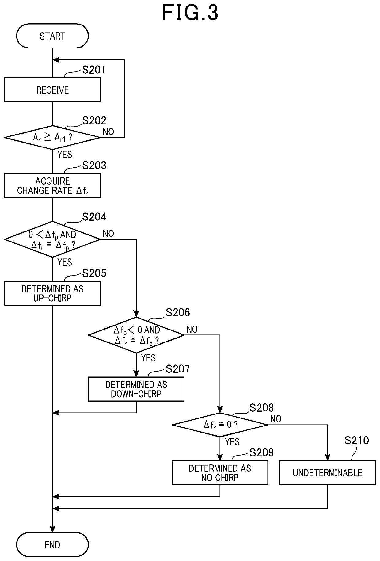
[0104]In the present embodiment, in step S204, whether Δfr≅ΔfA is satisfied is determined, and when it is determined that Δfr≅ΔfA is satisfied, the object detection device 1 proceeds to step 205. Further, in step S206, whether Δfr≅ΔfB is satisfied is determined, and when it is determined that Δfr≅ΔfB is satisfied, the object detection device 1 proceeds to step S207.
[0105]If the received wave includes the reflected wave...
PUM
 Abstract
Description
Claims
Application Information
 - R&D
- Intellectual Property
- Life Sciences
- Materials
- Tech Scout
- Unparalleled Data Quality
- Higher Quality Content
- 60% Fewer Hallucinations
Browse by: Latest US Patents, China's latest patents, Technical Efficacy Thesaurus, Application Domain, Technology Topic, Popular Technical Reports.
© 2025 PatSnap. All rights reserved.Legal|Privacy policy|Modern Slavery Act Transparency Statement|Sitemap|About US| Contact US: help@patsnap.com


