Timber clamping device

A clamping device and wood technology, applied in the direction of grinding machines, metal processing equipment, grinding/polishing equipment, etc., can solve the problems of uneven grinding, easy to appear wear marks, etc., and achieve the effect of preventing wood from falling

Inactive Publication Date: 2014-12-17
CHENGDU NONDO FURNITURE
View PDF0 Cites 1 Cited by
  • Summary
  • Abstract
  • Description
  • Claims
  • Application Information

AI Technical Summary

Problems solved by technology

[0004] The wood clamping device of the present invention, with its simple operation method, achieves the purpose of solving the problems of uneven grinding and easy occurrence of wear marks during wood processing

Method used


Image

  • Timber clamping device
  • Timber clamping device

Examples


Embodiment 1

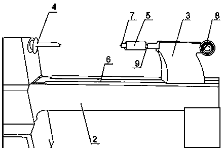
[0021] Such as figure 1 As shown, the clamping tool includes a support frame 1, a clamping mechanism 2, and the clamping mechanism 2 is arranged on the support frame 1. The clamping mechanism 2 includes a moving mechanism 3, a top chuck 4 and a guide rail 6, and the moving mechanism 3 Slidingly arranged on the guide rail 6, the top chuck 4 is connected to the support frame 1, the top chuck 4 is detachable, and the moving mechanism 3 is provided with a rotation mechanism 5 near the top chuck 4. During the wood grinding process, the wood is placed between the top chuck 4 and the end-face driven top chuck 7 on the rotating mechanism 5, and the moving mechanism 3 is slowly driven by the deceleration motor to clamp the log; The hand wheel 8 is shaken to adjust the rotation angle of the log, then it is fixed, and the required position is polished.

Embodiment 2

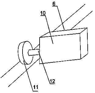
[0023] Such as figure 1 and figure 2 As shown, the present embodiment is based on Embodiment 1. The moving mechanism 3 includes a reduction motor 10, a base and a transmission wheel 12, the base is slidably arranged on the guide rail 6, and the reduction motor 10 and the transmission wheel 12 are placed Inside the base, the transmission wheel 12 is connected with the output shaft 11 of the reduction motor 10, and the transmission wheel 12 is in contact with the guide rail 6, and the rotating mechanism 5 is arranged on the base. The reduction motor 10 starts to rotate, and drives the transmission wheel 12 to move on the guide rail 6, thereby driving the whole base to move slowly, and then under the artificial assistance, the timber is clamped on the clamping mechanism.

Embodiment 3

[0025] Such as figure 1 As shown, this embodiment is based on Embodiment 2, and the front end of the rotating mechanism 5 is provided with an end-face driven top chuck 7 . The top chuck 7 driven by the end surface on the rotating mechanism 5 cooperates with the top chuck 4 on the support seat 1 to block the log to be polished, so as to avoid it accidentally falling during processing and affect the processing progress.


PUM


Abstract

The invention discloses a clamping tool. A timber clamping device comprises a supporting frame and a clamping mechanism. The clamping mechanism is arranged on the supporting frame. The clamping mechanism comprises a movable mechanism, a tip chuck and a guide rail. The movable mechanism is arranged on the guide rail in a sliding mode, the tip chuck is detachably connected with the supporting frame, and a rotating mechanism is arranged on the side, close to the tip chuck, of the movable mechanism. The rotating mechanism is arranged on a base. The rotating mechanism has the forwards-rotating function and the backwards-rotating function, and can rotate by 360 degrees, the rotating angle is set at will, and after the angle is adjusted, the rotating mechanism cannot rotate any more. The rotating angle of a timber is adjusted at any time through a hand wheel of the rotating mechanism, and the timber can be polished and processed conveniently. When the timber clamping device breaks down, the tip chuck can be dismounted and can be replaced conveniently. In the whole process, the timber is arranged between the movable mechanism and the tip chuck, the movable mechanism is adjusted to clamp the timber tightly, and the rotating mechanism drives the timber to rotate by any angle so that the timber can be processed conveniently.

Description

technical field [0001] The invention relates to a wood clamping device, in particular to a clamping tool for wood grinding and processing. Background technique [0002] With the increasing demand for forest products in the domestic and foreign markets, the output of domestic wood-based panels, furniture and paper-making products has continued to increase significantly, the consumption of wood has increased, and the market circulation has become active. Driven by the continuous increase in wood consumption, the price of wood has risen and the output of wood has continued to increase, which has promoted the development of domestic forestry and also promoted the growth of imports of wood products and waste paper. In the future, the demand for forest products in domestic and foreign markets will continue to increase, and domestic wood consumption will still maintain a certain growth. [0003] Therefore, with the increase of wood consumption, various wood processing technologies...

Claims


Application Information

Patent Timeline
Patent Type & Authority Applications(China)
IPC IPC(8): B24B5/04
CPCB24B5/04
Inventor 黄礼奎
Owner CHENGDU NONDO FURNITURE
Why Eureka
Try Eureka