Sensor installation device

A technology for installing devices and sensors, which is applied in the direction of supporting machines, mechanical equipment, machine platforms/supports, etc., which can solve problems such as inconvenient operation, limited position adjustment range, and changes, and achieve error compensation, large adjustment range, adjustment and locking The effect of synchronous completion

Active Publication Date: 2014-12-17
BEIJING NAURA MICROELECTRONICS EQUIP CO LTD
View PDF5 Cites 12 Cited by
  • Summary
  • Abstract
  • Description
  • Claims
  • Application Information

AI Technical Summary

Problems solved by technology

[0005] 1. It cannot directly compensate the angular deviation of the sensor when it is installed, and the position adjustment range is also limited
Especially when the transmitting end and receiving end of the laser beam sensor are far apart, even if there is a small non-parallel on the mounting surfaces on both sides, it will cause a large positional deviation of the beam at the transmitting end
[0006] 2. Inconvenient operation
When adjusting, you need to loosen the screws at various places first, adjust the position manually and keep it still, and then tighten the screws with the other hand to complete the fixation. There is a secondary tightening operation, which is not only inconvenient to operate, but also prone to adjustment due to secondary tightening The good position has changed again. In some inconvenient and narrow workstations, it even requires two people to cooperate to complete the adjustment.
[0007] 3. The position adjustment operation is completely realized by manually moving the position of the mounting parts in the vertical and horizontal directions, and it is difficult to achieve fine and accurate adjustment

Method used


Image

  • Sensor installation device
  • Sensor installation device
  • Sensor installation device

Examples


Embodiment

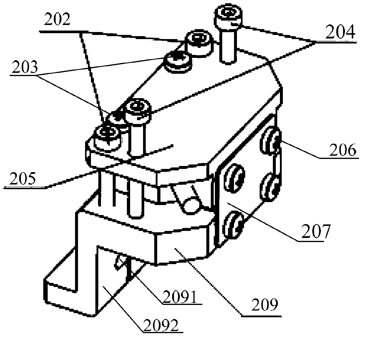
[0043] An embodiment of the present invention provides a sensor installation device, referring to figure 2 As shown, the device includes: an angle adjustment block 205, a movement adjustment block 209 and an elastic connector 207, wherein:

[0044] The angle adjustment block 205 and the movement adjustment block 209 are arranged in parallel, and the sensor (not shown) is fixedly connected with one end of the angle adjustment block 209, so that the sensor is positioned in the parallel space between the angle adjustment block 205 and the movement adjustment block 209, and the angle The adjustment block 205 is used to adjust the angle of the sensor; the moving adjustment block 209 is used to adjust the position of the sensor.

[0045] The elastic connector 207 is perpendicular to the angle adjustment block 205 and the mobile adjustment block 209, and the two ends of the elastic connector 207 are respectively fixedly linked with the side of the other end (that is, the end away fr...


PUM


Abstract

The invention discloses a sensor installation device, and relates to the field of semiconductor equipment manufacturing. The device can adjust the inclination angle of a sensor, synchronously achieves adjustment and locking and simplifies operation steps. The sensor installation device comprises an angle adjusting block, a moving adjusting block and an elastic connector. The angle adjusting block and the moving adjusting block are arranged in parallel, the sensor is fixedly connected with one end of the angle adjusting block, and accordingly the sensor is located in parallel space between the angle adjusting block and the moving adjusting block; the elastic connector is perpendicular to the angle adjusting block and the moving adjusting block, the two ends of the elastic connector are fixedly connected with the side face of the other end of the angle adjusting block and the side face of the moving adjusting block, and accordingly the angle adjusting block and the moving adjusting block are connected together; the elastic connector is bent in the direction towards or far away from the sensor to achieve adjustment of the depression angle or the elevation angle of the sensor; the moving adjusting block moves in the horizontal direction so as to adjust the position of the sensor.

Description

technical field [0001] The invention relates to the field of semiconductor equipment manufacturing, in particular to a sensor installation device. Background technique [0002] In various automation equipment, it is often necessary to use sensors to detect the action and position of the mechanism and feed back to the control system. Among them, the non-contact photoelectric sensor, especially the laser through-beam sensor, because of its non-contact, With the advantages of high precision, fast response, and long-distance detection, it is more and more widely used in automation equipment. [0003] The laser through-beam sensor is composed of two parts: the transmitter and the receiver. The laser beam projected by the transmitter has a small diameter (diameter Φ about 0.5 ~ 3mm) and is highly collimated. However, the light receiving window of the receiver is usually relatively small (diameter Φ about 5 ~ 8mm), so the two require precise alignment during installation, which pu...

Claims


Application Information

Patent Timeline
Patent Type & Authority Applications(China)
IPC IPC(8): F16M11/04F16M11/16
Inventor 张鹏
Owner BEIJING NAURA MICROELECTRONICS EQUIP CO LTD
Why Eureka
Try Eureka