
Lamp lifting device

A technology for lifting devices and lamps, which is applied to lighting devices, lighting auxiliary devices, components of lighting devices, etc., can solve problems such as damage to lifting devices, lamps falling, danger, etc., so as to ensure normal work, prevent free fall, and improve safety. sexual effect

Active Publication Date: 2014-12-17
OCEANKING DONGGUAN LIGHTING TECH +2
View PDF6 Cites 7 Cited by
  • Summary
  • Abstract
  • Description
  • Claims
  • Application Information

AI Technical Summary

Problems solved by technology

Due to the lack of protection devices in the prior art, the motor suddenly cuts off when it is working, and the lamp will fall under the action of gravity, which will affect the safety of the people under the lamp; in addition, when the motor is working abnormally, the motor speed is too fast to make the lamp rise and fall too fast , may exceed the bearing range of the steel wire rope and the entire lifting device, resulting in danger of wire rope breakage, or damage to the lifting device

Method used


Image

  • Lamp lifting device
  • Lamp lifting device
  • Lamp lifting device

Examples


Embodiment Construction

[0024] The following will clearly and completely describe the technical solutions in the embodiments of the present invention with reference to the drawings in the embodiments of the present invention.

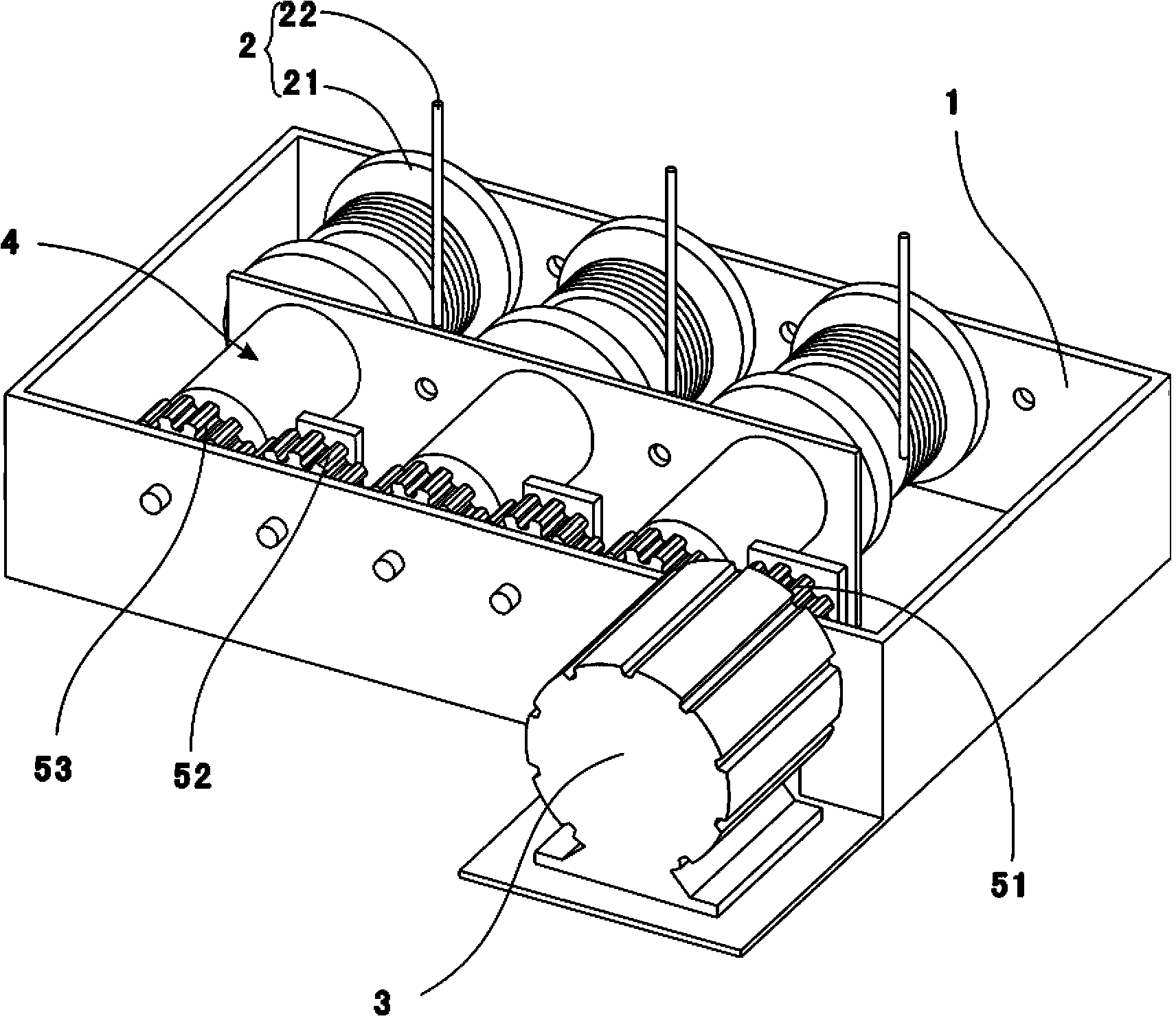
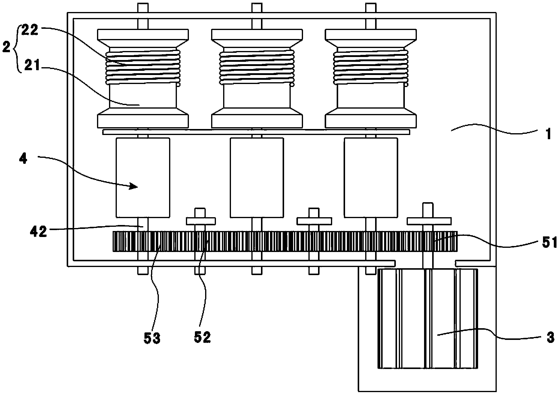
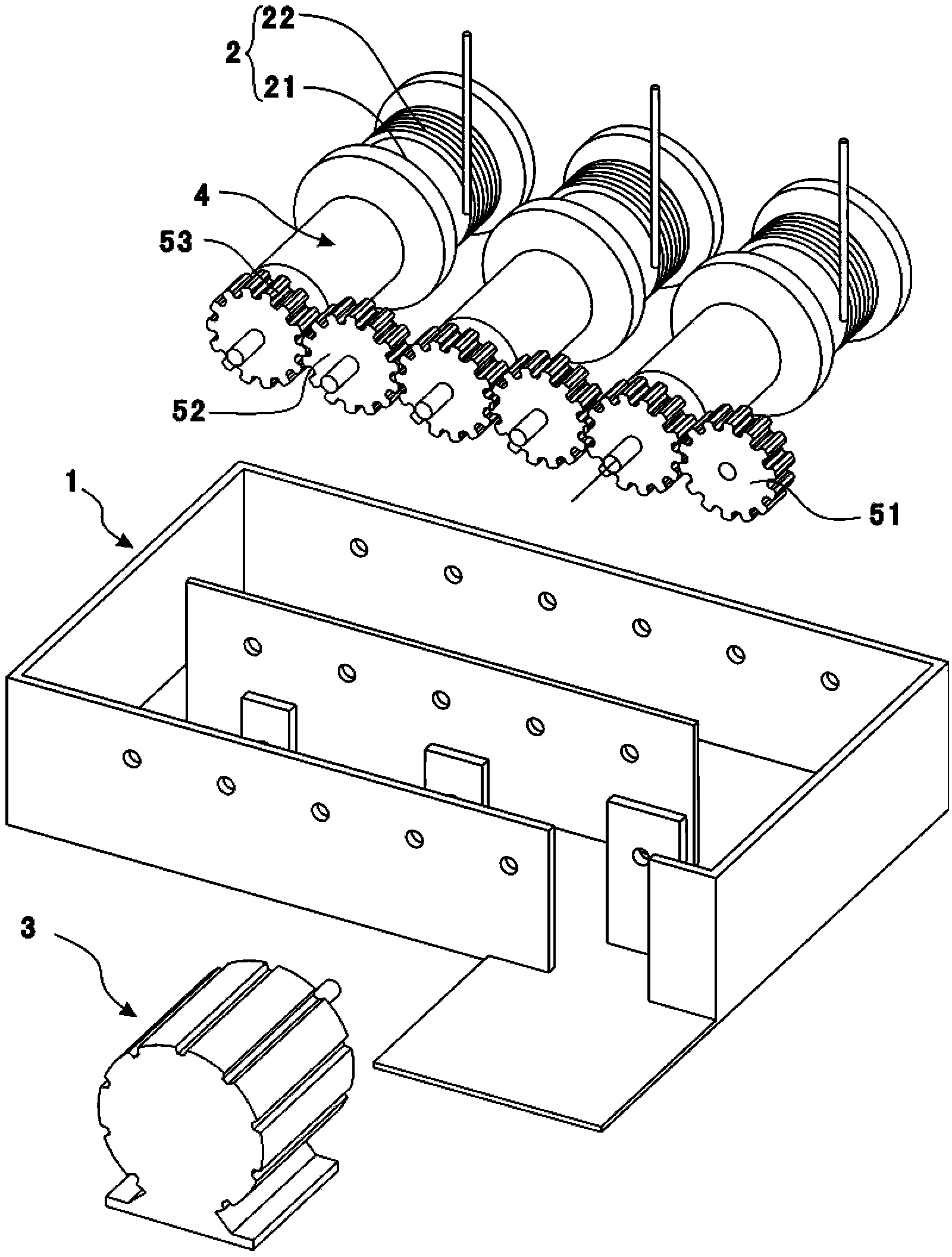
[0025] see Figure 1 to Figure 3 , is a schematic structural diagram of a lamp lifting device provided in a preferred embodiment of the present invention. The lamp lifting device includes a base 1 , a winding assembly 2 , a motor 3 and a protection assembly 4 . The motor 3 , the winding assembly 2 and the protection assembly 4 are all mounted on the base 1 . The winding assembly 2 includes a winding wheel 21 and a rope 22 , and the motor 3 is connected to the winding wheel 21 for driving the winding wheel 21 to rotate. The protection assembly 4 is connected to the reel 21 and is used to limit the rotation speed of the reel 21 .

[0026] The base 1 is a square shell with one side open, the motor 3 is fixed outside the base 1, and the winding assembly 2 and the protection ass...


PUM


Abstract

The invention discloses a lamp lifting device. The lamp lifting device comprises a base, a wire winding assembly, a motor and a protecting assembly, wherein the protecting assembly comprises a shell, a universal driving shaft, a flywheel, a pawl, an elastic piece and a limiting piece, the universal driving shaft is connected to the shell in the mode that the universal driving shaft rotates around itself in the axial direction and is in transmission connection with a wire winding wheel, the flywheel is arranged in the shell in a rotary mode and is fixed to the universal driving shaft in the circumferential direction, the pawl is provided with a rotary shaft end and a limiting end opposite to the rotary shaft end, the rotary shaft end is connected to the flywheel in a rotary mode, and a limiting groove is formed in the limiting piece. The wire winding wheel can drive the universal driving shaft and the flywheel to rotate when the wire winding wheel rotates, the pawl is hinged to the flywheel, when a lamp rise or fall at an overhigh speed, the rotating speed of the wire winding wheel and the rotating speed of the flywheel are too high, the pawl rotates under the effect of centrifugal force, the limiting end of the pawl is matched with the limiting groove, so that the flywheel stops rotating and is positioned, then the wire winding wheel is positioned, rising or falling of the lamp is stopped, in this way, free falling of the lamp is prevented or the lamp is prevented from rising or falling at an overhigh speed, stable rising and falling of the lamp are guaranteed, normal work of the lamp lifting device is guaranteed, and the safety performance of the lamp lifting device is improved.

Description

technical field [0001] The invention relates to a control device for lighting equipment, in particular to a lifting device for a lamp. Background technique [0002] In the field of large outdoor lamps such as high pole lamps and square lamps, the lamps are suspended at a high place, and the lamps can be raised and lowered by the lifting device to adjust the height of the lamps. In the prior art, a motor is generally used to directly drive a reel wound with a wire rope, and a lamp is driven up and down by a wire rope. Due to the lack of protection devices in the prior art, the motor suddenly cuts off when it is working, and the lamp will fall under the action of gravity, which will affect the safety of the people under the lamp; in addition, when the motor is working abnormally, the motor speed is too fast to make the lamp rise and fall too fast , may exceed the bearing range of the steel wire rope and the entire lifting device, resulting in danger of wire rope breakage, or ...

Claims


Application Information

Patent Timeline
Patent Type & Authority Applications(China)
IPC IPC(8): F21V21/38
Inventor 周明杰丁牛欢
Owner OCEANKING DONGGUAN LIGHTING TECH
Learn More