Check patentability & draft patents in minutes with Patsnap Eureka AI!

An anisotropic conductive film attaching device and a method for adjusting a cutter

An anisotropic conductive film and cutting knife technology, applied in the direction of circuits, electrical components, semiconductor devices, etc., can solve problems such as unguaranteed levels, affecting equipment operation, and abnormal quality, so as to improve the attachment yield and increase the service life Effect

Inactive Publication Date: 2017-09-26
HEFEI BOE OPTOELECTRONICS TECH +1
View PDF4 Cites 0 Cited by
  • Summary
  • Abstract
  • Description
  • Claims
  • Application Information

AI Technical Summary

Problems solved by technology

like figure 1 As shown, the cutter 1 is fixed between the base 2 and the fixed plate 3, and the fixed plate 3 and the base 2 are fastened by screws. Adjustment, after the adjustment is completed, lock the screw to fix the cutter, which will cause the cutter to shift left and right, so that the blade and the base 2 cannot be guaranteed to be level after the cutter is installed, and the blade is not parallel to the surface of the ACF to be cut, not only adjusting the consumption of the cutter After the adjustment is completed, the service life of the cutter is short (about one month), which may easily cause poor ACF sticking, affect the operation of the equipment, and cause abnormal quality

Method used


Image

  • An anisotropic conductive film attaching device and a method for adjusting a cutter
  • An anisotropic conductive film attaching device and a method for adjusting a cutter

Examples


Embodiment Construction

[0041] The structure and principle of the present invention will be described in detail below in conjunction with the accompanying drawings, and the examples given are only used to explain the present invention, not to limit the protection scope of the present invention.

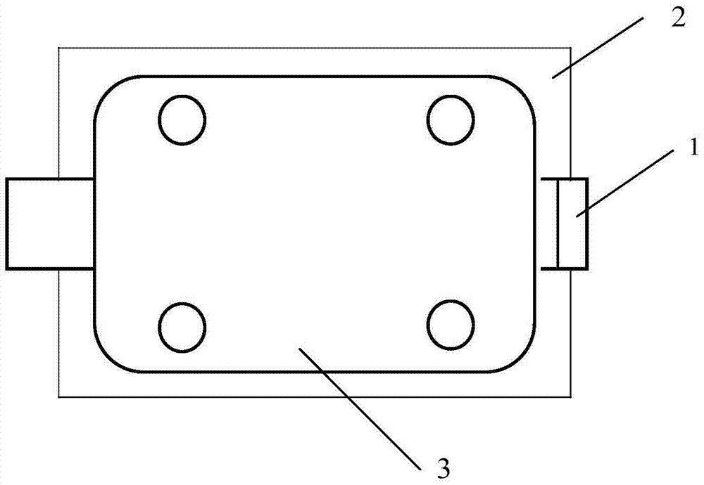
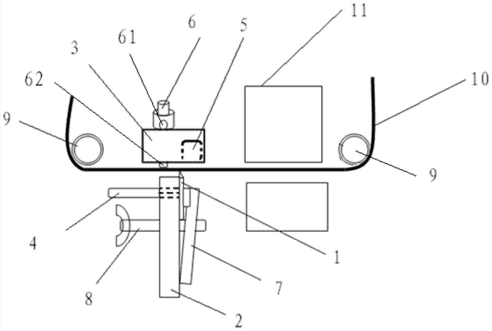
[0042] Such as figure 2 As shown, this embodiment provides a device for attaching an anisotropic conductive film 10, including

[0043] A cutter 1 for cutting the anisotropic conductive film 10 when the anisotropic conductive film 10 is moving;

[0044] A cutter 1 fixing mechanism for fixing the cutter 1;

[0045] The fixing mechanism of the cutter 1 comprises:

[0046] A fixing structure for fixing the cutter 1;

[0047] The first adsorption structure is arranged on one side of the cutter 1, and is used to absorb the cutter 1 when adjusting the cutter 1 so that the cutter 1 is located at a first position in a direction perpendicular to the moving direction of the anisotropic conductive film 10;

[0048...


PUM


Abstract

The invention relates to an attaching device of anisotropic conductive films and an adjustment method of a cutter. The attaching device comprises the cutter and a cutter fixture. The cutter is used for cutting an anisotropic conductive film when the anisotropic conductive film moves; the cutter fixture is used for fixing the cutter. The attaching device is characterized in that the cutter fixture comprises a fixing structure, a first suction structure and a second suction structure; the fixing structure is used for fixing the cutter; the first suction structure arranged on one side of the cutter is used for sucking the cutter so that the cutter is located at a first position in a direction perpendicular to a moving direction of the anisotropic conductive film while the cutter is under adjustment; the second suction structure opposite to the fixing structure comprises a first side parallel to the moving direction of the anisotropic conductive film; when the cutter is under adjustment, the second suction structure sucks the cutter so that a cutting edge of the cutter is in contact with the first side and that the cutting edge of the cutter is adjusted to a direction parallel to the moving direction of the anisotropic conductive film. The attaching device and the adjustment method have the advantages that the cutting edge of the cutter is parallel to the moving direction of the anisotropic conductive film, and attachment yield of anisotropic conductive films is increased.

Description

technical field [0001] The invention relates to automatic production equipment in the TFT Module (array substrate assembly) manufacturing industry, in particular to an anisotropic conductive film (ACF) sticking device in a Bonding (combination) machine and a method for adjusting a cutter. Background technique [0002] At present, in the TFT Module Process (array substrate component process flow), the ACF attachment place and ACF cutter of each equipment of the OLB (Out Lead Bonding) machine adopt the traditional fixing mechanism and adjustment method. Such as figure 1 As shown, the cutter 1 is fixed between the base 2 and the fixed plate 3, and the fixed plate 3 and the base 2 are fastened by screws. Adjustment, after the adjustment is completed, lock the screw to fix the cutter, which will cause the cutter to shift left and right, so that the blade and the base 2 cannot be guaranteed to be level after the cutter is installed, and the blade is not parallel to the surface of...

Claims


Application Information

Patent Timeline
Patent Type & Authority Patents(China)
IPC IPC(8): H01L21/28H01L21/77
CPCB26D7/2628
Inventor 方飞陆晓明何文兵唐先珍徐蕾龚小卫
Owner HEFEI BOE OPTOELECTRONICS TECH
Features
  • R&D
  • Intellectual Property
  • Life Sciences
  • Materials
  • Tech Scout
  • Unparalleled Data Quality
  • Higher Quality Content
  • 60% Fewer Hallucinations
Learn More