
A crank-connecting rod type agricultural implement lifting device for micro tillage machine

A technology of crank connecting rods and agricultural machinery, which is applied to the lifting device of agricultural machinery, agricultural machinery and implements, and adjustment devices. It can solve problems such as inconvenient operation, single function, and limited use range, so as to improve production efficiency and reduce labor intensity. , good practical effect

Inactive Publication Date: 2016-10-12
HENAN UNIV OF SCI & TECH
View PDF9 Cites 0 Cited by
  • Summary
  • Abstract
  • Description
  • Claims
  • Application Information

AI Technical Summary

Problems solved by technology

However, due to the small size and structure of the micro-tiller, the space that can be arranged is also small, so many ordinary agricultural machinery cannot be directly arranged on the micro-tiller, thus limiting its own scope of use.
Especially for some miniature rotary tillers that have requirements for the depth of tillage, in order to meet their requirements for the depth of rotary tillage, many manufacturers make the tiller heavier and rely on the gravity of the tiller itself to meet the requirements for the depth of tillage; now the market There is also a rotary tiller that directly removes the two walking wheels of the tiller and installs a rotary tiller on the walking shaft. Although this method meets the requirements for the depth of cultivation, it is difficult to reach the two ends of the cultivated land. At the same time, because there is no support of the walking wheels, the rotary tiller cannot be lifted, and it needs to be lifted artificially, which is time-consuming and laborious, and the operation is inconvenient. Moreover, this kind of tiller can only be equipped with a single agricultural implement, and its function is relatively single, which cannot meet the needs of agriculture. Diverse job requirements

Method used


Image

  • A crank-connecting rod type agricultural implement lifting device for micro tillage machine
  • A crank-connecting rod type agricultural implement lifting device for micro tillage machine

Examples


Embodiment Construction

[0015] Below in conjunction with accompanying drawing and specific embodiment the present invention is described in further detail:

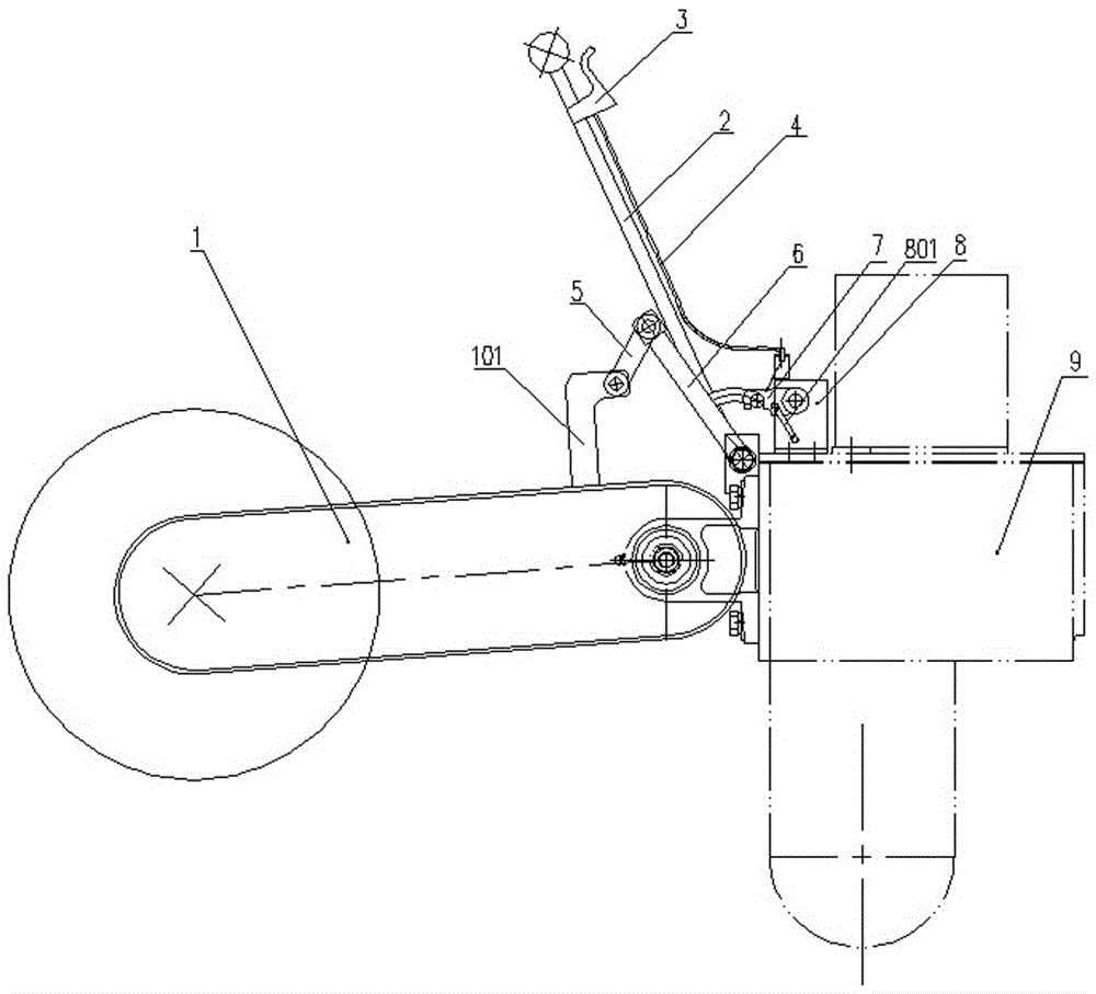
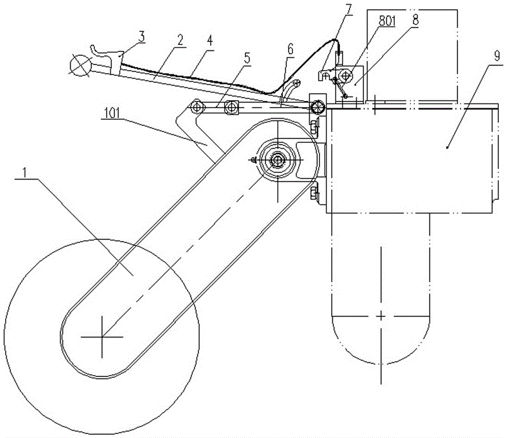
[0016] A crank-link type agricultural implement lifting device for a tiller, comprising an agricultural implement 1, a frame 9, a lifting lever 2 arranged on the frame 9, a crank rod 6 and a lock hook frame 8, the agricultural implement 1 One end is hinged on the frame 9, and a connecting rod 101 is also arranged on the agricultural implement 1, and the lifting lever 2 and the crank rod 6 are arranged on the frame 9 through a rotating shaft, and the rotation of the lifting lever 2 can drive The crank rod 6 coaxial with it moves up and down, and an intermediate rod 5 is hinged at the end of the crank rod 6, and the intermediate rod 5 is hinged with the connecting rod 101 arranged on the agricultural implement 1. When the lifting lever 2 rotates, it can pass through the crank rod. The linkage between 6 and the middle rod 5 drives the agricultural ...


PUM


Abstract

A crank connecting rod type agricultural implement lifting device for a mini-tiller comprises an agricultural implement, a frame, a lifting lever, a crank rod and a lock hook rack, wherein the lifting lever, the crank rod and the lock hook rack are arranged on the frame, the agricultural implement is hinged to the frame, a connection rod is further arranged on the agricultural implement, one end of the lifting lever and one end of the crank rod are both fixedly connected with a rotary shaft arranged on the frame, the tail end of the crank rod is hinged to a middle rod hinged to the connection rod, and the lifting lever can drive the agricultural implement to move up and down by means of linkage between the crank rod and the middle rod when rotating. A limit lock hook is arranged on the lock hook frame, a fixing pin shaft is arranged on the crank rod, and an operation handle is arranged at the top end of the lifting lever, is connected with the limit lock hook through a pull wire, and can control matched locking or unlocking of the limit lock hook and the fixing pin shaft through the pull wire. By means of the lifting device, different agricultural implements can be hung on the mini-tiller and lifted freely and conveniently, and effective control over the tilling depth is achieved, therefore, labor intensity is reduced, and the tilling efficiency is increased.

Description

technical field [0001] The invention relates to the technical field of agricultural machinery equipment, in particular to a crank-link type agricultural machinery lifting device for a tiller. Background technique [0002] Because of its simple structure and easy operation, the micro tillage machine is widely used in vast areas of our country, especially in the southwest and some hilly areas. However, due to the small size and structure of the micro-tiller, the space that it can be arranged is also small, causing many ordinary agricultural machinery to be directly arranged on the micro-tiller, thus limiting its own scope of use. Especially for some miniature rotary tillers that have requirements for the depth of tillage, in order to meet their requirements for the depth of rotary tillage, many manufacturers make the tiller heavier and rely on the gravity of the tiller itself to meet the requirements for the depth of tillage; now the market There is also a rotary tiller that ...

Claims


Application Information

Patent Timeline
Patent Type & Authority Patents(China)
IPC IPC(8): A01B63/00
Inventor 姬江涛王东洋贾世通刘卫想张志红邓明俐杜新武贺智涛金鑫何亚凯
Owner HENAN UNIV OF SCI & TECH
Learn More