
Elastic compressing mechanism

A technology of elastic pressing and cohesion, which is applied to workpiece clamping devices, manufacturing tools, etc., can solve the problems of poor universality of elastic pressing mechanism, no buffer function, complex structure, etc., and achieves small shape, low production cost, and processing. Create simple effects

Active Publication Date: 2014-12-24
BOZHON PRECISION IND TECH CO LTD
View PDF5 Cites 2 Cited by
  • Summary
  • Abstract
  • Description
  • Claims
  • Application Information

AI Technical Summary

Problems solved by technology

[0002] When assembling and operating the product, sometimes it is necessary to press the product from the side. At this time, a pressing mechanism is needed to press the product through the top block. In order to ensure that the product is not damaged, the top block is in the process of ejection. It is necessary to control the ejection speed, so an elastic pressing mechanism is needed to realize the above functions. The elastic pressing mechanism of the existing mechanism has poor versatility, and the structure is relatively complicated, and it does not have a buffer function during the pressing process.

Method used


Image

  • Elastic compressing mechanism
  • Elastic compressing mechanism
  • Elastic compressing mechanism

Examples


Embodiment Construction

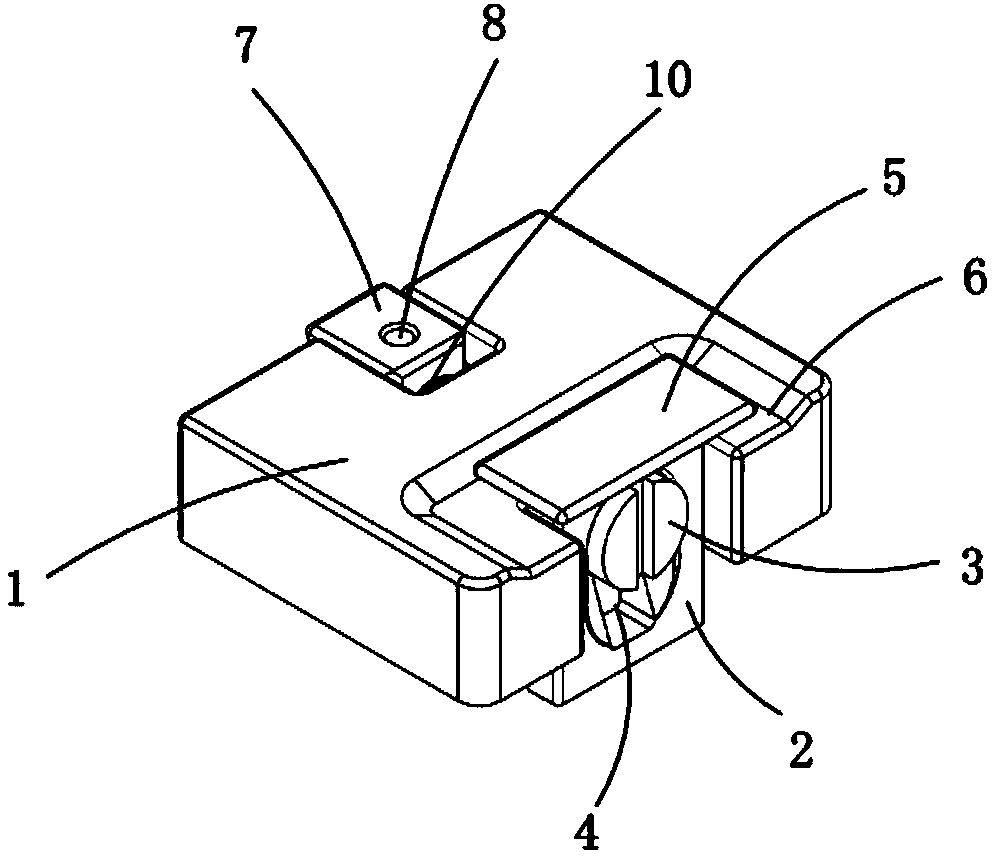
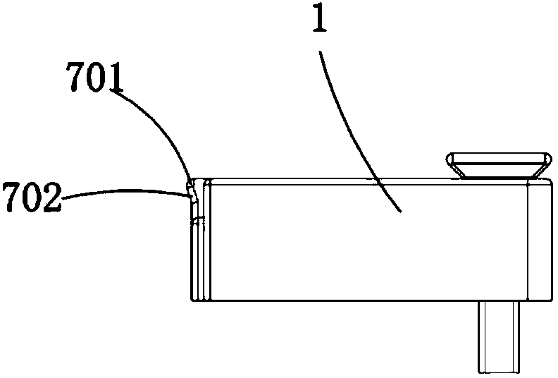
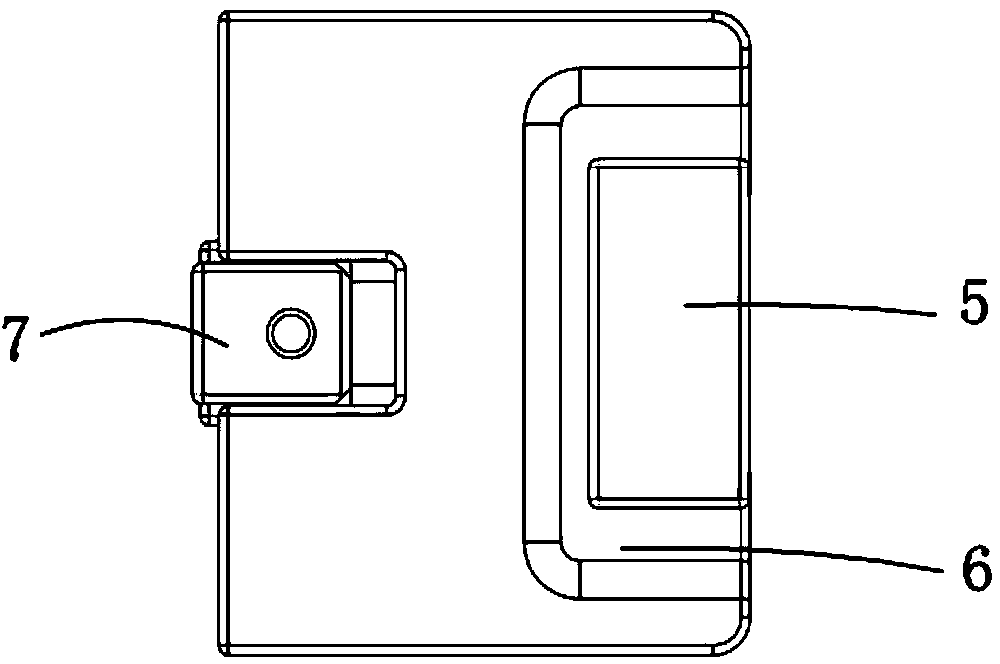
[0021] Examples, see attached Figure 1~6 , an elastic pressing mechanism, including a fixed seat 1, and also includes a handle 2 and a push rod 3, a racetrack-shaped through hole 4 is provided on the handle, and internal helical teeth are arranged in the race-track-shaped through hole, and the push rod is There are external helical teeth, and the pull handle and the ejector rod are movably connected together through the mutual meshing of the internal helical teeth and the external helical teeth.

[0022] The fixing seat is fixed on the jig or the equipment panel by means of screw connection, which facilitates the fixing of the whole mechanism.

[0023] The upper end of the pull handle is connected to a carrier board 5, and a groove 6 is provided on the fixing seat at the carrier board to facilitate manual operation of the carrier board.

[0024] The ejector rod passes through the fixed seat, and the left end of the ejector rod is connected with a jacking block 7, the ejector...


PUM


Abstract

The invention relates to an elastic compressing mechanism. The elastic compressing mechanism comprises a fixed seat, a pulling handle and a carrier rod, wherein the pulling handle and the carrier rod are connected together in a tooth mesh manner; the upper end of the pulling handle is connected with a support plate; the carrier rod passes through the inside of the fixed seat; the left end of the carrier rod is connected with a top block; a stepped groove is formed in the left end of the fixed seat; a spring is connected between the top block and the stepped groove of the fixed seat; the spring is arranged on the carrier rod; the left side and the right side of the top block are provided with a stepped surface respectively; the stepped surface of the top block is just positioned on the stepped groove; the support plate is pulled to drive the pulling handle to move; the pulling handle and the carrier rod are in tooth mesh with each other to drive the carrier rod to move, the carrier rod retracts, and the support plate is pressed down to drive the pulling handle to move, and the carrier rod is ejected to compress a product. The elastic compressing mechanism is small in appearance, is wide in application range, can be arranged on any equipment or jig for use, is easy and convenient to operate, occupies small space, is low in manufacturing cost, and is easy to machine and manufacture.

Description

Technical field: [0001] The invention relates to the field of pressing mechanism equipment, and more specifically relates to an elastic pressing mechanism. Background technique: [0002] When assembling and operating the product, sometimes it is necessary to press the product from the side. At this time, a pressing mechanism is needed to press the product through the top block. In order to ensure that the product is not damaged, the top block is in the process of ejection. The ejection speed needs to be controlled, so an elastic pressing mechanism is needed to realize the above functions. The elastic pressing mechanism of the existing mechanism has poor versatility, complicated structure, and no cushioning function in the pressing process. Invention content: [0003] The purpose of the present invention is to provide an elastic pressing mechanism aimed at the deficiencies of the prior art, which can be installed on any equipment or jig, and is easy and convenient to operat...

Claims


Application Information

Patent Timeline
Patent Type & Authority Applications(China)
IPC IPC(8): B25B11/00
CPCB25B11/00B25B11/02
Inventor 吕绍林杨愉强王建福卫新志
Owner BOZHON PRECISION IND TECH CO LTD
Learn More