Yarn nozzle lifting device in flat knitting machine

A lifting device and yarn feeder technology, used in textiles and papermaking, weft knitting, knitting, etc., can solve the problems of easy failure, high work coordination requirements, and high overall component cost

Active Publication Date: 2014-12-24
NINGBO CIXING
View PDF7 Cites 6 Cited by
  • Summary
  • Abstract
  • Description
  • Claims
  • Application Information

AI Technical Summary

Problems solved by technology

However, the driving structures of the existing intarsia yarn feeders are very complicated and cumbersome, not only the cost of the overall components is high, but also the requirements for work coordination are high, and failures are prone to occur

Method used


Image

  • Yarn nozzle lifting device in flat knitting machine
  • Yarn nozzle lifting device in flat knitting machine
  • Yarn nozzle lifting device in flat knitting machine

Examples


Embodiment Construction

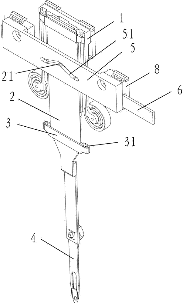
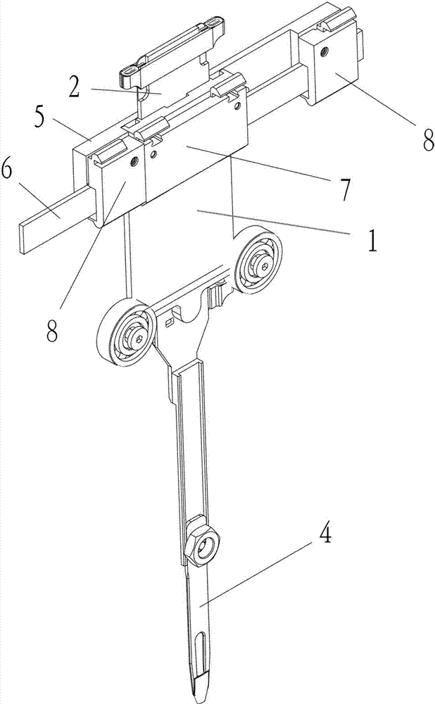
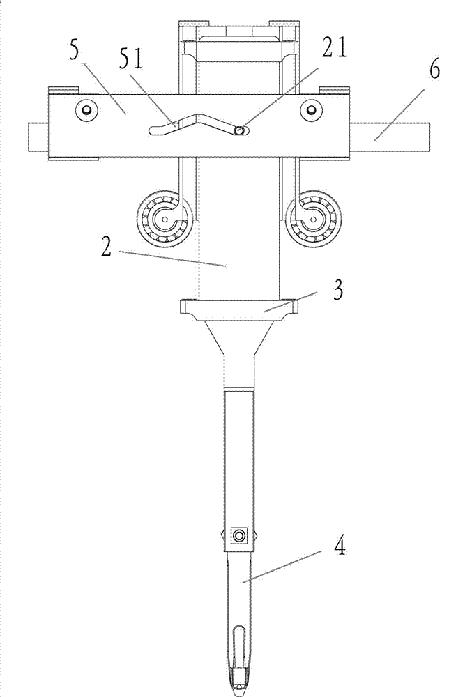
[0011] See attached picture. This embodiment includes Us seat 1, Us handle 2, porcelain eye seat 3, yarn feeder 4, timing belt cover 5 and timing belt 6; there is a rectangular slideway in the middle of the Us seat 1, Us handle 2 The upper end is placed on the rectangular slideway in the middle of the Us seat 1, the yarn feeder 4 is fixed on the lower end of the Us handle 2, the porcelain eye seat 3 is fixed on the Us handle 2, and the two ends of the porcelain eye seat 3 have porcelain eyes 31 ; There is a drive pin 21 on the url handle 2, a limit block 11 is fixed behind the urn seat 1, and there is a movable channel between the url seat 1 and the limit block 7; the timing belt 6 is placed on the urn In the movable channel between the seat 1 and the limit block 7; the synchronous belt cover plate 5 is located above the handle 2, and the two ends of the synchronous belt cover plate 5 are fixed on the synchronous belt 6 through the fixed block 8; the synchronous belt There is...


PUM


Abstract

The invention discloses a yarn nozzle lifting device in a flat knitting machine. The yarn nozzle lifting device comprises a Uz seat, a Uz handle, a synchronous belt cover plate and a synchronous belt. The upper end of the Uz handle is arranged in the middle of the Uz seat, and a drive pin is arranged on the Uz handle. A limiting block is fixed behind the Uz seat, and a movable channel is formed between the Uz seat and the limiting block. The synchronous belt is arranged in the movable channel between the Uz seat and the limiting block. The synchronous belt cover plate is arranged above the Uz handle, and the two ends of the synchronous belt cover plate are fixed to the synchronous belt through fixing blocks. An inverted-V-shaped movable groove is formed in the middle of the synchronous belt cover plate, and the drive pin on the Uz handle is arranged in the inverted-V-shaped movable groove of the synchronous belt cover plate. The motion track of a yarn nozzle is controlled by dragging the synchronous belt cover plate by the synchronous belt, and the yarn nozzle carries out weaving when at the low position of the inverted-V-shaped movable groove. The yarn nozzle does not carry out weaving when at the high position of the inverted-V-shaped movable groove, and therefore the yarn nozzle collision problem is solved.

Description

technical field [0001] The invention belongs to the technical field of knitting machinery, in particular to a yarn feeder lifting device in a flat knitting machine. Background technique [0002] The computerized flat knitting machine controls the yarn feeder to start or stop working anywhere within the weaving width range by computer signals. In order to weave more complex intarsia structures more effectively, most computerized flat knitting machines also need to be equipped with special intarsia yarn feeders. , After knitting a certain color area, the intarsia yarn feeder needs to rise according to the program and leave the working state to avoid collision with the knitting needles of the next color area. Most of the existing intarsia yarn feeders have the function of lifting the yarn feeder, which can drive the yarn feeder to move up and down through the corresponding driving structure according to the specific work needs. However, the drive structure of the existing inta...

Claims


Application Information

Patent Timeline
Patent Type & Authority Applications(China)
IPC IPC(8): D04B15/00
Inventor 孙平范胡跃勇罗再杰张乔治
Owner NINGBO CIXING
Why Eureka
Try Eureka