Sliding block and oblique ejector combination mould for forming grooves in peripheral inner sidewalls of product

A combined molding and slider technology, applied in the field of metal die-casting molds and plastic injection molds, can solve problems such as collisions, mold installation, and debugging difficulties

Inactive Publication Date: 2016-08-24
牟维军
View PDF0 Cites 5 Cited by
  • Summary
  • Abstract
  • Description
  • Claims
  • Application Information

AI Technical Summary

Problems solved by technology

The mold with grooves on the inner side wall around the product formed by the combination of the slider and the inclined top solves the problem that the moving core of the shrinking core mold mechanism collides when it moves to the center of the mold, and solves the problem that the core pulling mechanism of the inner slider is caused by the slider and the inclined The pressure block and the inclined guide post are all installed inside the mold, which makes the installation and debugging of the mold very difficult.

Method used


Image

  • Sliding block and oblique ejector combination mould for forming grooves in peripheral inner sidewalls of product
  • Sliding block and oblique ejector combination mould for forming grooves in peripheral inner sidewalls of product
  • Sliding block and oblique ejector combination mould for forming grooves in peripheral inner sidewalls of product

Examples


Embodiment Construction

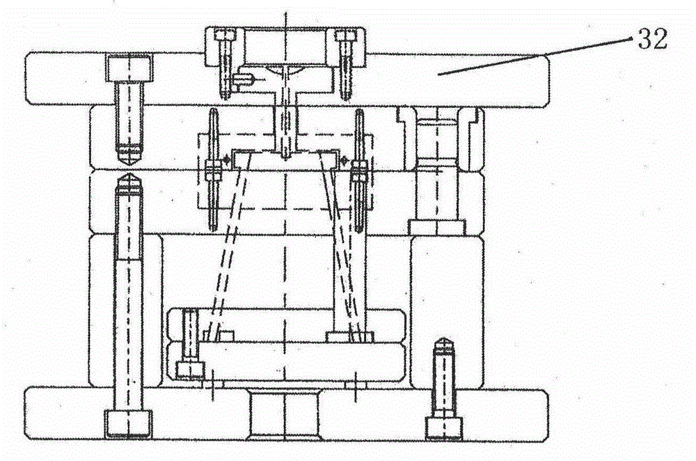
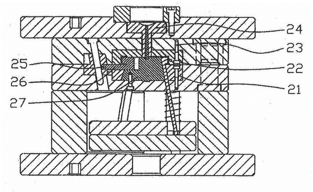
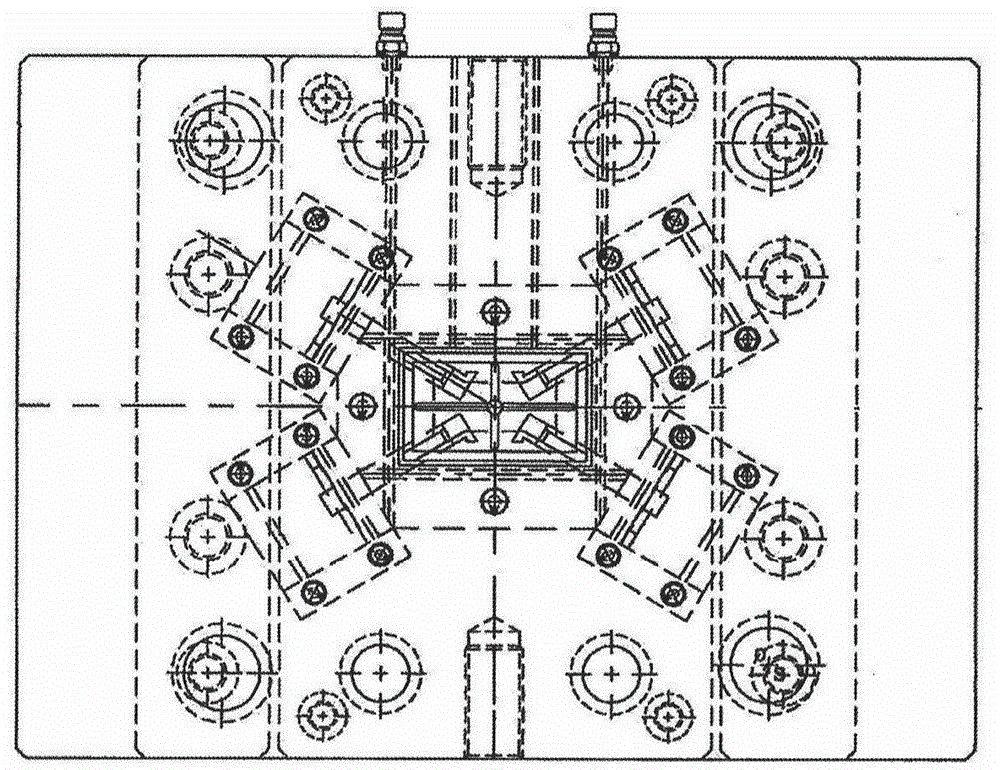
[0033]As shown in the figure, it is a mold that combines the slider and the inclined top to form the groove on the inner side wall of the product. As shown in the product part in (8), since the product is a large through-frame, and there are grooves on the inner side wall of the product, if Using the inner slider core-pulling mechanism to form the product, the inner side of the mold must be installed with sliders, oblique pressure blocks and oblique guide columns. At the same time, the four grooves on the inner wall of the product require high dimensional accuracy, and each groove must be equipped with a set of sliders. The core-pulling at the groove can only be completed by using block, inclined guide post and inclined pressing block. Therefore, there are many parts in the mold, which brings great difficulties to the manufacture and installation of the mold. For example, the mechanism of shrinking core is used to form the product At the groove, when the mold is opened and the ...


PUM


Abstract

The invention discloses a sliding block and oblique ejector combination mould for forming grooves in the inner sidewalls of a product. The sliding block and oblique ejector combination mould is characterized in that first oblique ejectors (14) and second oblique ejectors (17) are arranged on an ejection pin plate (9); the forming parts of the first oblique ejectors (14) and the second oblique ejectors (17) are mutually locked with sliding block mould cores (26) arranged on sliding blocks (19); forming positions for the grooves of the inner sidewalls of the product (5) are formed after the first oblique ejectors (14) and the second oblique ejectors (17) are mutually contacted and locked tightly with the sliding block mould cores (26); during mould disassembly, the sliding block mould cores (26) slide toward the inner sides of the mould; the pushing-out force of the first oblique ejectors (14) and the second oblique ejectors (17) is small, and meanwhile, a very large moving space is provided; during pushing-out, the first oblique ejectors (14) and the second oblique ejectors (17) do not collide with one another.

Description

technical field [0001] The invention relates to a metal die-casting mold and a plastic injection mold, and is a mold for forming grooves on the inner side walls around a product formed by combining a slide block and an inclined top. Background technique [0002] At present, in the mold manufacturing industry, the mold mechanism used for products with grooves around the inner wall of the product has the following two structures (1) shrinkage core mechanism, which is to open a T-shaped groove on the core of the movable mold side , Install a movable core that can slide in the opened T-shaped slot. When the movable core is closed, it forms a groove on the inner wall of the product. When the mold is opened, the core installed in the movable template moves backward, and the movable core is in the During the movement of the core moving backward, the core-pulling action is performed in the inner direction to complete the core-pulling of the inner wall around the product. After the c...

Claims


Application Information

Patent Timeline
Patent Type & Authority Applications(China)
IPC IPC(8): B29C45/26B29C45/40B22D17/22
Inventor 牟维军
Owner 牟维军
Why Eureka
Try Eureka