Synchronizer ring for a synchronization unit of a manual transmission and synchronization unit with such a synchronizer ring

A technology of synchronous unit and synchronous ring, which is applied in the field of synchronous ring, can solve problems such as reduction of cone angle, damage to the function of synchronous unit, and decrease in shifting comfort, and achieve the effects of reduced engagement torque, simple manufacturing technology, and high friction torque

Active Publication Date: 2014-12-24
HOERBIGER ANTRIEBSTECHN HLDG
View PDF9 Cites 11 Cited by
  • Summary
  • Abstract
  • Description
  • Claims
  • Application Information

AI Technical Summary

Problems solved by technology

Of course, the cone angle cannot be reduced arbitrarily, since cone angles below a limit of about 5° to 7° can cause an undesired self-locking effect of the synchronization unit
If the cone angle moves into the s

Method used


Image

  • Synchronizer ring for a synchronization unit of a manual transmission and synchronization unit with such a synchronizer ring
  • Synchronizer ring for a synchronization unit of a manual transmission and synchronization unit with such a synchronizer ring
  • Synchronizer ring for a synchronization unit of a manual transmission and synchronization unit with such a synchronizer ring

Examples


Embodiment Construction

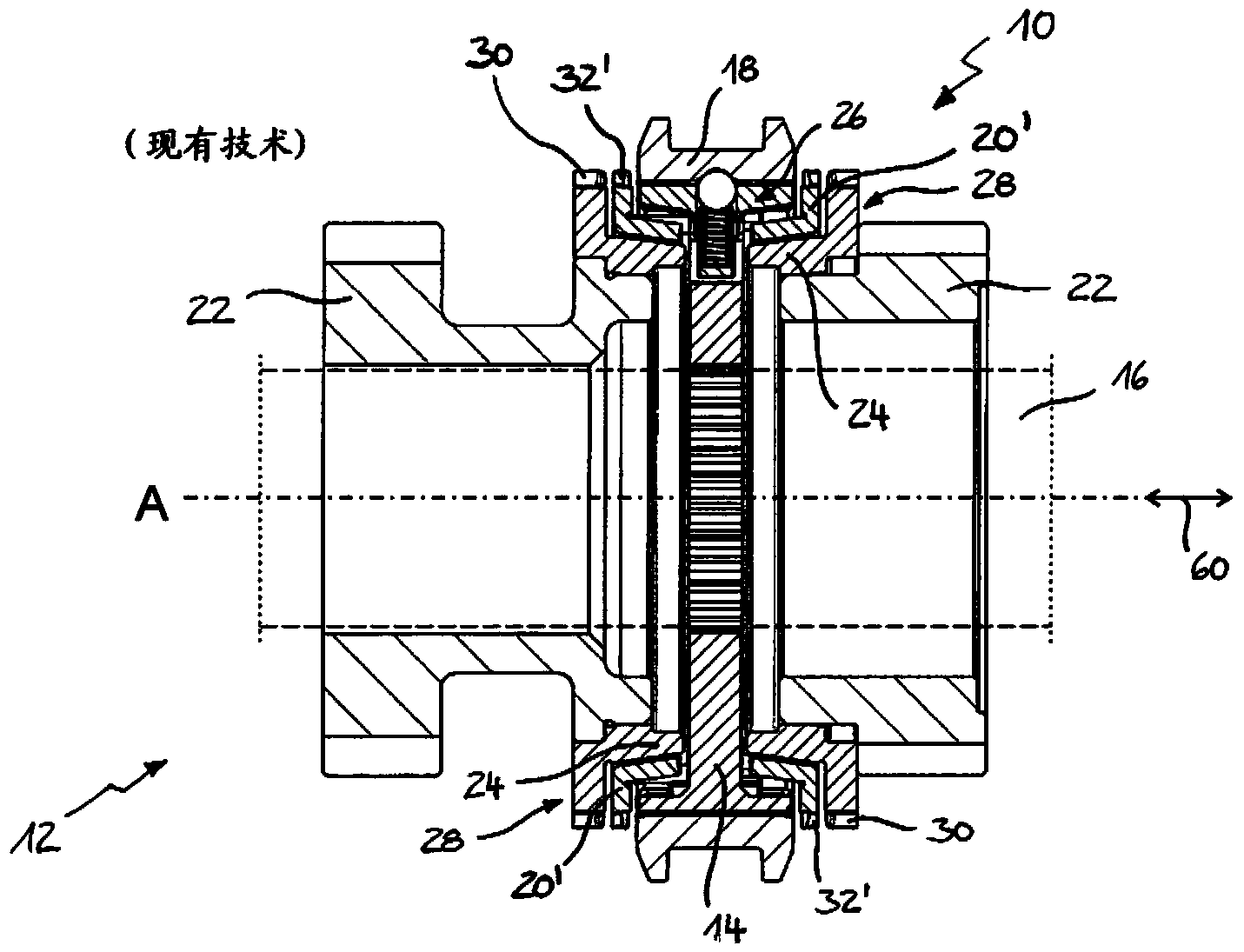
[0029] figure 1 The synchronizing unit 10 of the transmission 12 is shown, which has a synchronizing body 14 , which is mounted in a rotationally fixed manner on a transmission shaft 16 and is rotatable about the transmission axis A; and a shifting sleeve 18 opposite to the The synchronizing body 14 is arranged in a rotationally fixed manner, but axially displaceable. The synchronizing unit 10 also comprises a conventional synchronizing ring 20 ′ according to the prior art for coupling the synchronizing body 14 with the gear wheel 22 of the transmission 12 via a frictional connection, wherein the synchronizing ring 20 ′ is coupled with the synchronizing body 14 in the circumferential direction 48 linked, but with limited rotation. Furthermore, a friction cone 24 is provided, which is fixedly connected to the gear wheel 22 and can be brought into frictional contact with the synchronizing ring 20'. The friction cone 24 is, for example, part of a clutch body 28, which according...


PUM


Abstract

The invention relates to a synchronizer ring (20) for a synchronization unit (10) of a gearbox (12), with a locking ring (34) having an annular axis (A) and a locking toothing (32) and a coaxial with the lock ring (34) disposed separate cone ring (36) having a first conical surface (38) having a first cone angle ([alpha]) and a radially opposite second conical surface (40) with a second cone angle ([beta]), wherein the first cone surface (38) in the installed state of the synchronizer ring (20) to a gangradseitigen friction cone (24) of the synchronization unit (10) and the second conical surface (40) at a conical counter surface (42) of the locking ring (34) abuts, wherein the locking ring (34) and the cone ring (36) mutually associated abutment surfaces (44, 46) which couple the locking ring (34) and the cone ring (36) in the circumferential direction (48) , and wherein the stop surfaces (44, 46) of the locking ring (34) and / or of the cone ring (36) relative to the ring axis (A) are at least partially inclined such that the second conical surface (40) and the conical counter surface (42) at a acting between the locking ring (34) and the cone ring (36) are torque loaded axially away from one another.

Description

technical field [0001] The invention relates to a synchronizing ring for a synchronizing unit of a transmission and to a synchronizing unit having such a synchronizing ring. Background technique [0002] The synchronizing unit is a conical friction clutch which, when actuated, generates a frictional torque and blocks shifting axially due to the locking geometry as long as there is a rotational speed difference between the synchronizing body and the gear wheels of the transmission Engagement sets. In order to achieve rapid rotational speed compensation, it is generally sought that the synchronizing unit provides the highest possible friction torque with a predetermined axial shifting force. [0003] In order to increase the friction torque, multi-cone synchronizers are used today, especially in the low gears of motor vehicles, but they lead to a more complex construction of the synchronization unit, a greater material requirement and a greater high weight. [0004] It is a...

Claims


Application Information

Patent Timeline
IPC IPC(8): F16D23/02
CPCF16D23/025F16D23/06F16D2023/0681
Inventor 奥特马尔·贝克
Owner HOERBIGER ANTRIEBSTECHN HLDG
Why Eureka
Try Eureka