Fixture for machining bolt ball on common lathe

A common lathe, bolt ball technology, applied in the direction of manufacturing tools, metal processing equipment, metal processing machinery parts, etc., can solve the problems of large operation error, affecting processing accuracy, time-consuming and laborious, and achieve fast and convenient process and improve processing accuracy. , the effect of convenient and quick operation

Pending Publication Date: 2018-09-28
HEZE UNIV
View PDF1 Cites 4 Cited by
  • Summary
  • Abstract
  • Description
  • Claims
  • Application Information

AI Technical Summary

Problems solved by technology

This bolt ball processing positioning fixture has the following disadvantages: (1) When installing the bolt ball on the clamping mandrel, one hand needs to fix one end of the clamping mandrel with an inner square wrench, and the other hand fixes the datum of the bolt ball The threaded hole is tightened with the external thread of the clamping mandrel. Since the bolt ball made of cast iron is relatively heavy, this operation process is not only time-consuming and laborious, but also easily causes the bolt ball to fall out of the hand, causing the guide rail and bed of the ordinary lathe to be smashed or even the operator. Injured by smashing; (2) Relying on the manual rotation of the horizontal and vertical angle dials to adjust the angle, the operation error is large and cannot be fine-tuned, which affects the machining accuracy; (3) Since the center of gravity of the bolt ball may not be at the center of the ball, it is difficult to rotate the vertical angle The bolt ball must be held during the panning process. Once you let go, the vertical angle pan will rotate, which is complicated and inconvenient to operate; (4) When adjusting the angle, you need to loosen the lock nut first, and then tighten the lock nut after the adjustment is completed. High labor intensity and low production efficiency

Method used


Image

  • Fixture for machining bolt ball on common lathe
  • Fixture for machining bolt ball on common lathe
  • Fixture for machining bolt ball on common lathe

Examples


Embodiment Construction

[0018] In order to clearly illustrate the technical features of this solution, the specific implementation of the present invention will be further described below according to the accompanying drawings.

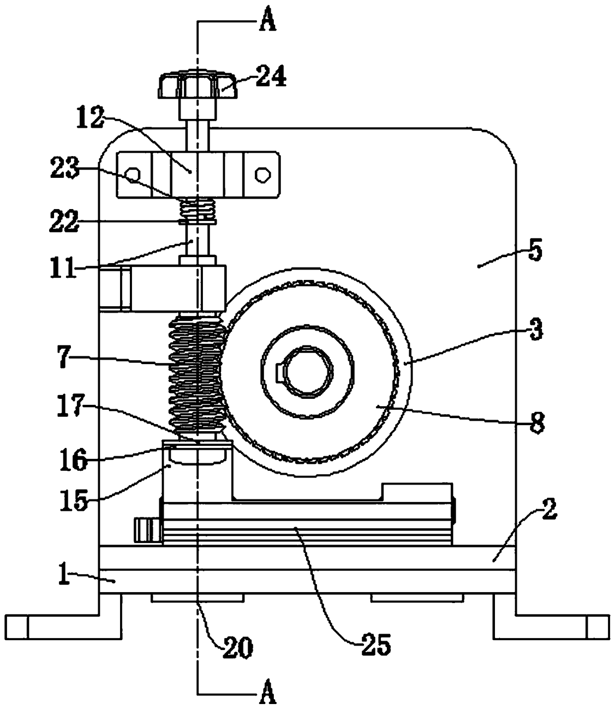
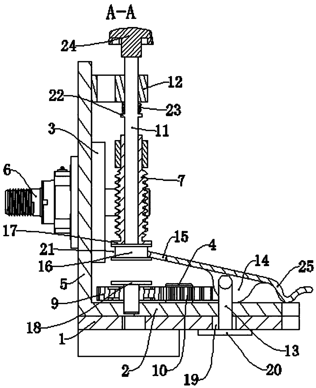
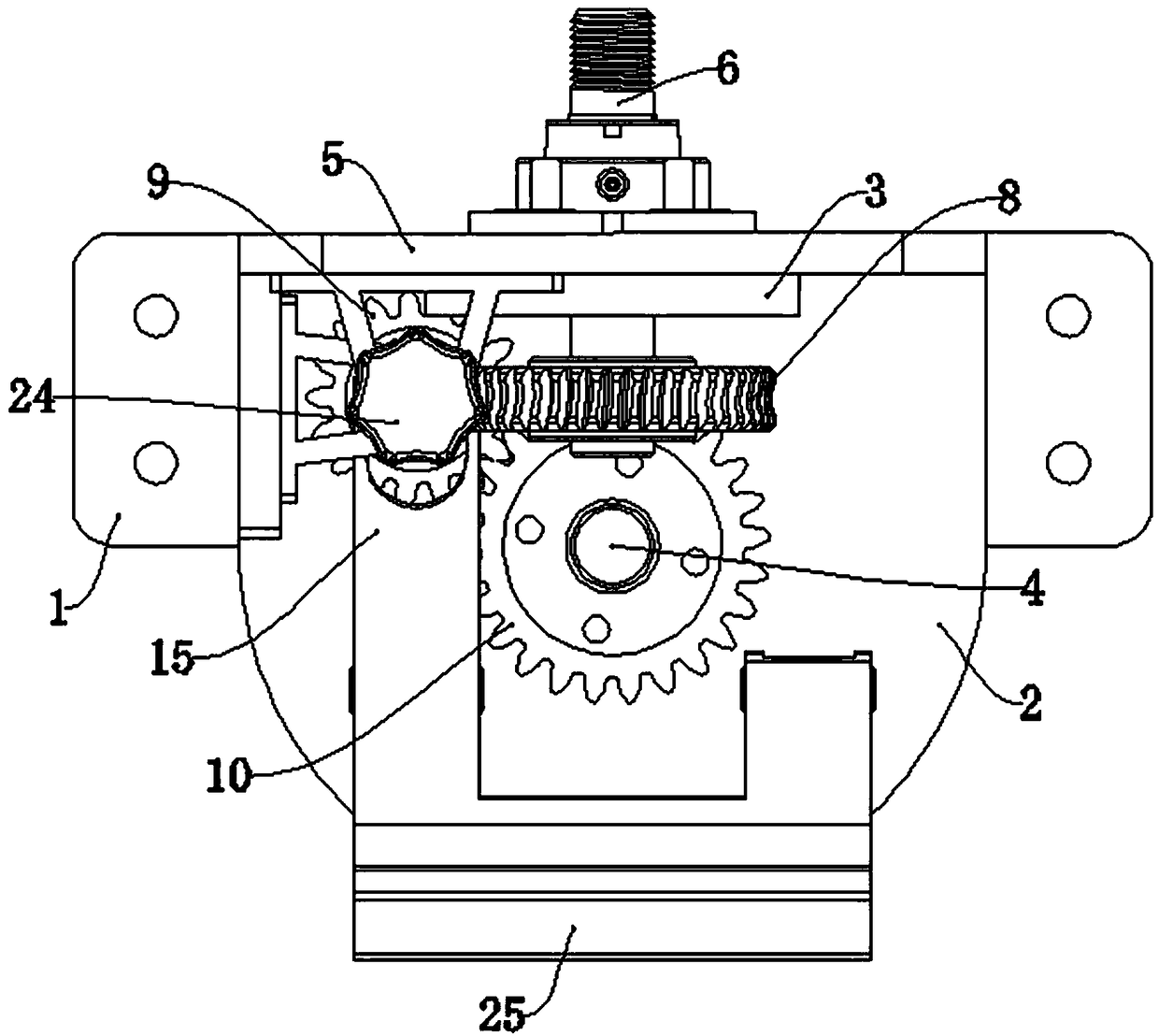
[0019] Figure 1 to Figure 7 It shows the fixture for processing bolt balls on ordinary lathes of the present invention, a fixture for processing bolt balls on ordinary lathes, including a base 1, a horizontal angle plate 2, a vertical angle plate 3, a worm 7, a worm wheel 8, and a planetary gear 9. Sun gear 10, transmission shaft 11, shaft sleeve 12, locking pin 13, eccentric wheel 14 and shift fork 15.

[0020] The top of the base 1 is fixed with a vertical shaft 4, and the horizontal angle disc 2 is slidably installed above the base 1 through the vertical shaft 4. The horizontal angle disc 2 can rotate around the vertical shaft 4 and can rotate along the axis of the vertical shaft 4. to swipe.

[0021] The horizontal angle plate 2 is provided with a vertical plate 5, an...


PUM


Abstract

The invention relates to the technical field of bolt ball machining process equipment, in particular to a fixture for machining a bolt ball on a common lathe. The fixture comprises a base, a horizontal angle scale, a vertical angle scale, a worm, a worm gear, a planetary gear, a sun gear, a transmission shaft, a shaft sleeve, lock pins, an eccentric wheel and a shifting fork. Compared with the prior art, the fixture for machining the bolt ball on the common lathe has the beneficial effects that (1) the clamping efficiency of the bolt ball is improved and the vertical angle scale is prevented from being rotated during machining through the self-locking capability of the worm transmission; (2) the fine adjustment can be performed, the operating error is small, and the machining precision isimproved; (3) the horizontal angle scale is locked through the eccentric wheel and the lock pins, and the operation is efficient and convenient, so that the production efficiency is improved; and (4)the transmission shaft can be driven to vertically slide through the rotation of the eccentric wheel, the fixture is more convenient and efficient during operation through the linkage function, and the production efficiency is improved.

Description

technical field [0001] The invention relates to the technical field of bolt ball processing technology equipment, in particular to a fixture used for ordinary lathes to process bolt balls. Background technique [0002] The bolt ball is an essential part of the grid structure, and there are multiple internal threaded holes on it for connecting with the rods. The utility model patent with the application number 200920218210.2 discloses a bolt ball processing positioning fixture, including a base, a horizontal angle plate, a vertical angle plate and a clamping mandrel, etc. The horizontal angle plate is rotatably installed on the base and tightened by a lock nut. The horizontal angle plate is provided with a vertical wall plate, and the vertical angle plate is rotatably installed on the vertical wall plate and fastened by a lock nut. The clamping mandrel is arranged in the aperture of the vertical angle plate, and one end of the clamping mandrel is provided with an external th...

Claims


Application Information

Patent Timeline
Patent Type & Authority Applications(China)
IPC IPC(8): B23Q3/06B23Q1/25
CPCB23Q1/25B23Q3/06B23Q3/062
Inventor 江峰祝凤金张东方吕桂志沈勇
Owner HEZE UNIV
Why Eureka
Try Eureka