End cap for lamp tube and lighting device with end cap

A technology for lighting devices and end caps, which is applied in the direction of lighting devices, lighting auxiliary devices, lighting device components, etc., and can solve problems such as unfavorable safety hazards, high production costs, and increased volume of lighting devices

Active Publication Date: 2014-12-24
LEDVANCE GMBH
View PDF8 Cites 1 Cited by
  • Summary
  • Abstract
  • Description
  • Claims
  • Application Information

AI Technical Summary

Problems solved by technology

However, this solution will bring unfavorable safety hazards due to the increased v...

Method used


Image

  • End cap for lamp tube and lighting device with end cap
  • End cap for lamp tube and lighting device with end cap
  • End cap for lamp tube and lighting device with end cap

Examples


Embodiment Construction

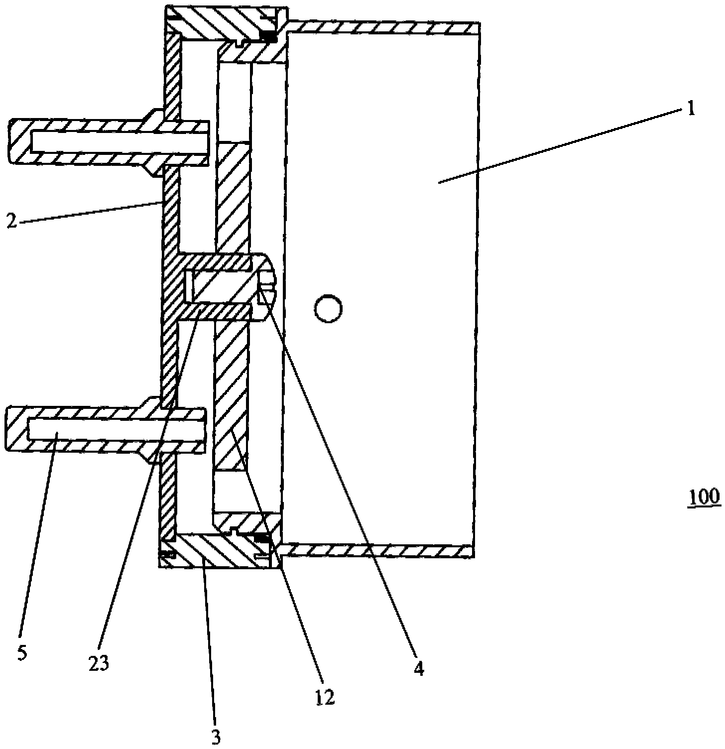
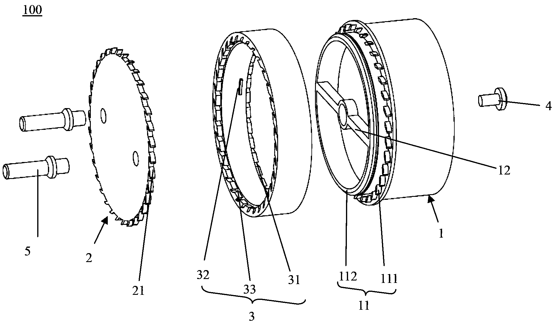
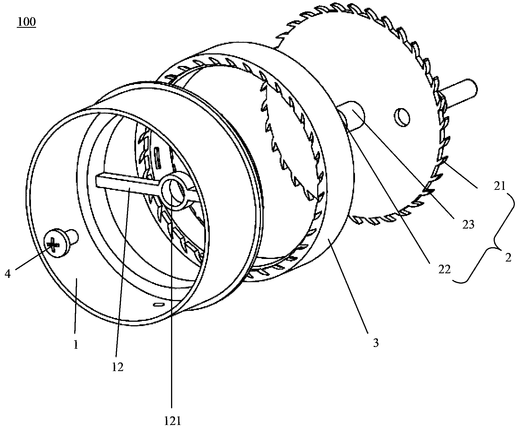
[0028] According to an embodiment of the present invention, the designed end cap 100 has main parts such as an assembly ring 1, a rotating ring 3 and a cover plate 2, such as figure 1 as shown, figure 1 is a cross-sectional view of an end cap 100 according to the present invention. It can be seen from the figure that the end cover 100 includes an assembly ring 1 , a rotating ring 3 and a cover plate 2 sequentially in the axial direction, and the purpose of assembling the end cover 100 can be realized by connecting the above three main parts to each other. Wherein, a support beam 12 is provided in the end cover 100, and a through hole is also provided on the support beam 12. In addition, a cylindrical rotating shaft 23 is also designed on the cover plate 2, so that the bolt 4 passes through the through hole and The rotating shaft 23 is connected to realize the purpose of connecting the assembly ring 1 , the rotating ring 3 and the cover plate 2 . The structure of the end cap ...


PUM


Abstract

The invention relates to an end cap for a lamp tube of a lighting device. The end cap comprises a fitting ring and a cap board; the fitting ring is fixedly mounted at one end of the lamp tube through a fitting end; the cap board is used for closing the fitting ring at an open end. The end cap further comprises a rotating ring; the rotating ring is mounted between the fitting ring and the cap board at the open end; the cap board rotatably closes the fitting ring through the rotating ring. In addition, the invention further relates to the lighting device with the end cap.

Description

technical field [0001] The invention relates to an end cover for a lamp tube of an illuminating device and an illuminating device using the end cover. Background technique [0002] With the widespread application and rapid development of LED technology, lighting devices using LEDs as light sources have also been widely used, such as daily bulbs, small spotlights, and stage lighting. With the further development of lighting devices, LED lighting devices with light sources for wide-range lighting are receiving more and more attention in terms of their packaging, and there are more and more requirements for them in terms of industrial protection, such as waterproof and dustproof. higher. Among them, in order to meet people's requirements for rotatable tubular LEDs, more and more LED lighting devices of this type are appearing on the market. Most rotatable LED lighting devices have complex structures and require a large space, and because the installation position of the drive...

Claims


Application Information

Patent Timeline
IPC IPC(8): F21V17/10F21V23/06F21Y101/02
CPCF21V23/003F21K9/272F21K9/278F21K9/65F21V14/02F21V21/30F21Y2103/10F21Y2115/10
Inventor 何俊男张云松刘全生聂誓俊
Owner LEDVANCE GMBH
Why Eureka
Try Eureka