Connecting rod and internal combustion engine

a technology of connecting rods and internal combustion engines, which is applied in the direction of shafts, bearings, rotary bearings, etc., can solve the problems of high production and assembly costs, easy wear, etc., and achieve the effects of reducing the good rotatability of the eccentric lever, and low weight of the connecting rod

Active Publication Date: 2017-02-14
DR ING H C F PORSCHE AG
View PDF11 Cites 1 Cited by
  • Summary
  • Abstract
  • Description
  • Claims
  • Application Information

AI Technical Summary

Benefits of technology

[0010]The invention relates to a connecting rod with an eccentric lever that has at least one eccentric lever segment. The eccentric lever segment is positioned in front of and / or behind the small end bearing eye, as seen in the axial direction of the eccentric. The or each eccentric lever segment is connected for conjoint rotation to the eccentric. The or each eccentric lever segment, an end face positioned adjacent to the respective eccentric lever segment of the small end bearing eye, and an adjacent end face of the eccentric each have a beveled contour. Thus, the eccentric can be connected in a simple manner to the or to each eccentric lever segment and tooth systems on the eccentric and on the eccentric lever are not needed. Thus, a low weight is achieved while reducing the outlay on production and assembly and susceptibility to wear.
[0011]The eccentric lever may have at least one eccentric lever segment. The or each eccentric lever segment may be positioned in front of and / or behind the small end bearing eye, as seen in the axial direction of the eccentric and may be connected for conjoint rotation to the eccentric. An end of each eccentric lever segment that is connected to the eccentric rods has a contour indented in the direction of the eccentric rods. Thus, the eccentric can be connected easily to the or to each eccentric lever segment of the eccentric lever. Accordingly, the tooth systems on the eccentric and on the eccentric lever can be dispensed with, thereby achieving a low weight, with a reduced outlay on production and assembly and improved wear.
[0013]The two end faces of the small end bearing eye, the two end faces of the eccentric and the two eccentric lever segments may extend parallel to one another in a lower section thereof and obliquely to one another in an upper section thereof for further reducing the weight of the connecting rod.
[0014]The entire adjustment range of the eccentric lever may be configured so that inflection lines in the contour of the eccentric lever segments at which the mutually parallel sections of the eccentric lever segments merge into the mutually oblique sections of the eccentric lever segments may lie above inflection lines in the contour of the axial end faces of the small end bearing eye at which the mutually parallel sections of the end faces of the small end bearing eye merge into the mutually oblique sections of the end faces of the small end bearing eye. The inflection lines in the contour of the eccentric lever segments and inflection lines in the contour of the axial end faces of the eccentric preferably extend directly adjacent to one another. It is thereby possible to ensure good rotatability of the eccentric lever combined with low weight of the connecting rod.
[0015]The eccentric lever segments positioned in front of the two end faces of the small end bearing eye have, at their ends, via which they are connected to the eccentric rods, an indented contour, reducing the distance between the eccentric lever segments. Thus, the weight of the connecting rod can be further reduced.
[0016]Indentation lines at ends of the eccentric lever segments preferably are configured so that when an eccentric rod engaging on ends of the eccentric lever segments has entered to the maximum extent into the respective hydraulic chamber, the indentation lines formed at this end of the eccentric lever segments extend parallel to a connecting-rod main body contour facing the respective eccentric rod. Thus, good rotatability of the eccentric lever and a low weight of the connecting rod are achieved.

Problems solved by technology

Connecting the eccentric to the eccentric lever by the intermeshing teeth requires a high outlay on production and assembly and is susceptible to wear.

Method used


Image

  • Connecting rod and internal combustion engine
  • Connecting rod and internal combustion engine
  • Connecting rod and internal combustion engine

Examples


Embodiment Construction

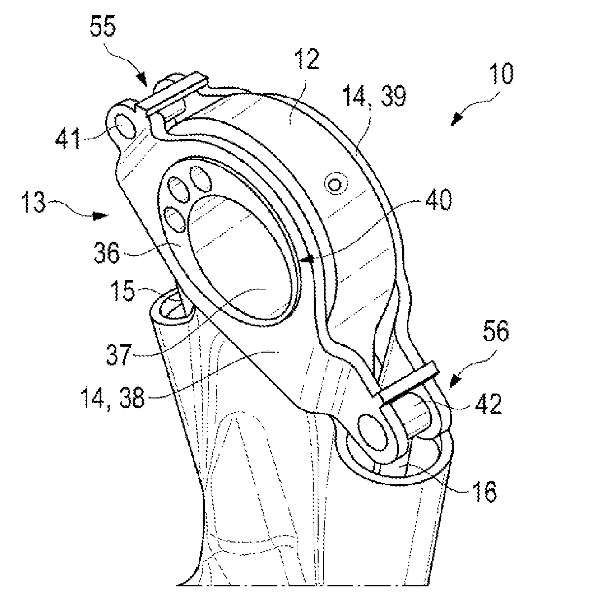
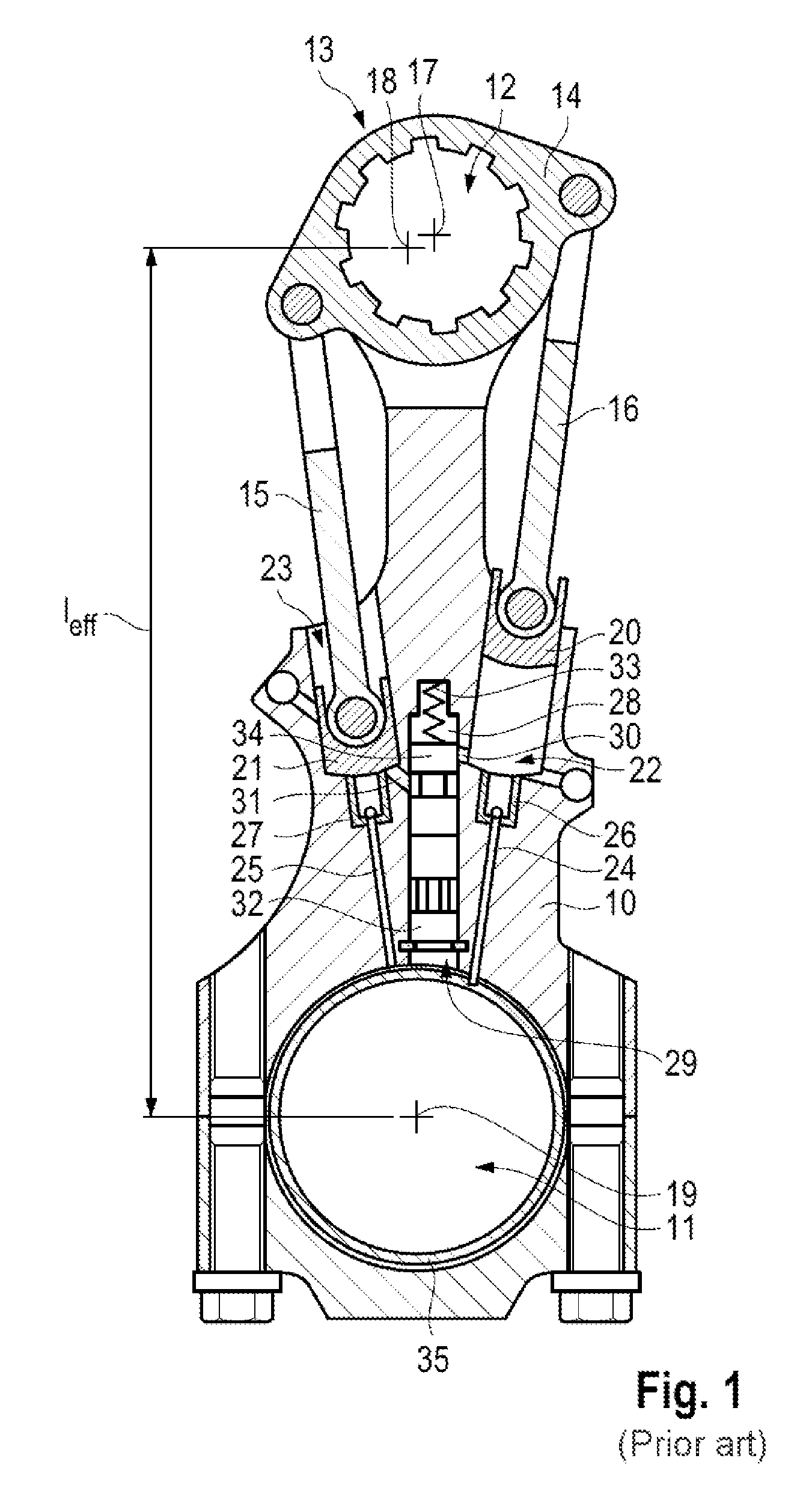
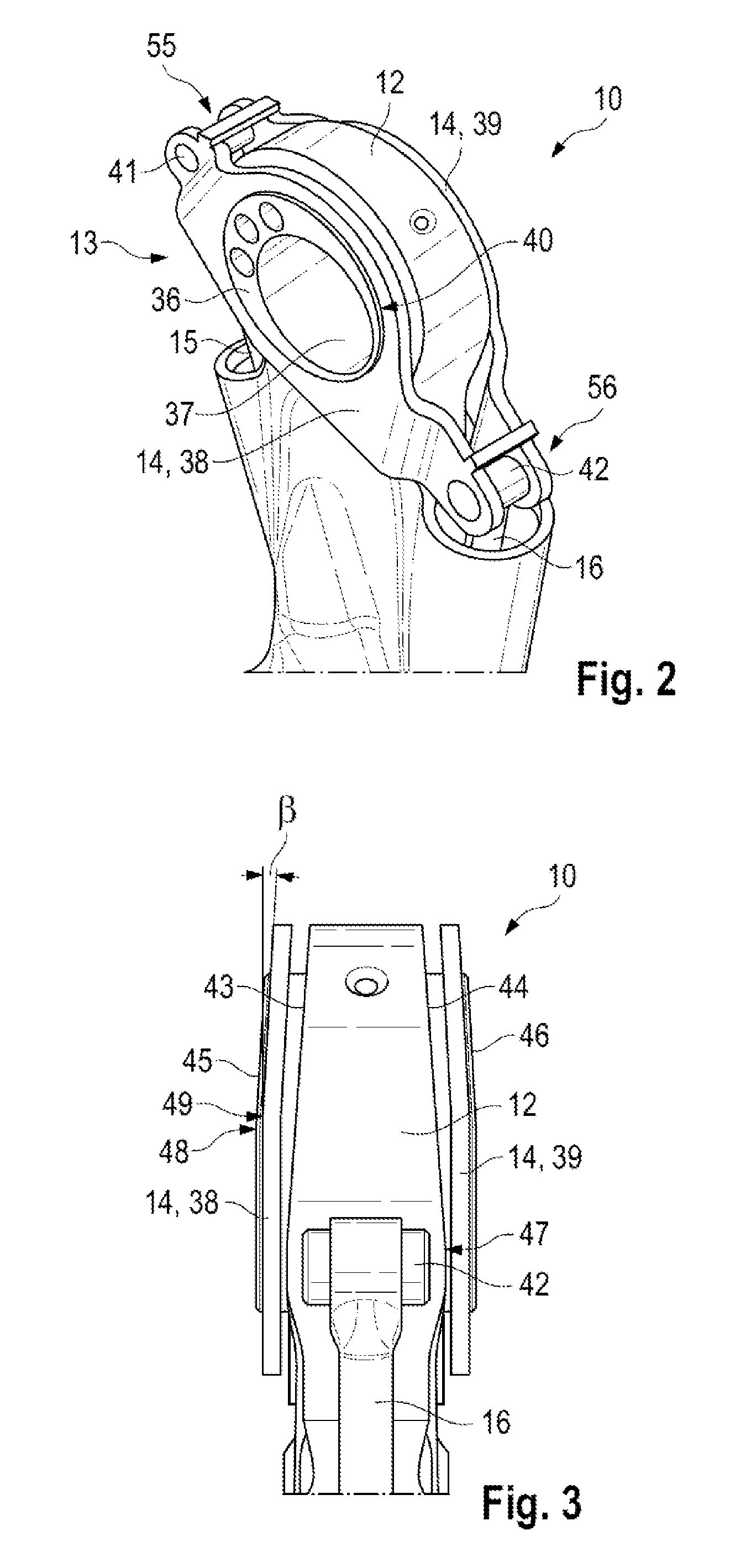
[0028]An internal combustion engine with an adjustable compression ratio has at least one, preferably several, cylinders. Each cylinder has a piston that is coupled by a connecting rod 10 to a crankshaft of the internal combustion engine.

[0029]One end of each connecting rod 10 has a small end bearing eye 12 and an opposite end has a big end bearing eye 11. The big end bearing eye 11 of each connecting rod 10 engages on a crankshaft bearing journal of the crankshaft so that a connecting rod bearing shell is positioned between the crankshaft bearing journal and the big end bearing eye, and a lubricating oil film can build up between the connecting rod bearing shell and the crankshaft bearing journal.

[0030]An internal combustion engine with an adjustable compression ratio has an eccentric adjustment device 13 in the region of each connecting rod 10 for adjusting the effective connecting rod length of the respective connecting rod 10. The eccentric adjustment device 13 has an eccentric ...


PUM


Abstract

A connecting rod (10) has a big end bearing eye (11) for connection to a crankshaft, a small end bearing eye (12) for connection to a piston of a cylinder, and an eccentric adjustment device (13) for adjusting an effective connecting rod length. The eccentric adjustment device (13) has an eccentric (36) that interacts with an eccentric lever (14), and eccentric rods (15, 16) that the eccentric lever (14). The eccentric lever (14) has segments (38, 39) positioned axially in front of and behind the small end bearing eye (12). Each eccentric lever segment (38, 39) is connected to the eccentric (36) for conjoint rotation. Each eccentric lever segment (38, 39), end faces (43, 44) of the small end bearing eye (10) adjacent the respective eccentric lever segment (38, 39), and adjacent end faces (45, 46) of the eccentric (36) have a beveled contours.

Description

CROSS REFERENCE TO RELATED APPLICATION[0001]This application claims priority under 35 USC 119 to German Patent Appl. No. 10 2014 100 585.6 filed on Jan. 20, 2014, the entire disclosure of which is incorporated herein by reference.BACKGROUND[0002]1. Field of the Invention[0003]The invention relates to a connecting rod for an internal combustion engine and to an internal combustion engine.[0004]2. Description of the Related Art[0005]DE 10 2010 016 037 A1 and FIG. 1 herein show a known connecting rod of an internal combustion engine having an adjustable compression ratio. With reference to FIG. 1, the connecting rod 10 has a big end bearing eye 11 and a small end bearing eye 12. The big end bearing eye 11 is used to connect the connecting rod 10 to a crankshaft (not shown in FIG. 1) and the small end bearing eye 12 is used to connect the connecting rod 10 to a cylinder piston (not shown in FIG. 1) of the internal combustion engine. The connecting rod 10 is assigned an eccentric adjustm...

Claims


Application Information

Patent Timeline
Patent Type & Authority Patents(United States)
IPC IPC(8): F02B75/04F16C7/06
CPCF02B75/045F02B75/044F16C7/06Y10T74/2151F16C2360/22F16C23/10
Inventor PAUL, MICHAEL
Owner DR ING H C F PORSCHE AG
Why Eureka
Try Eureka