Centrifugal acceleration emission device based on motor driving

A centrifugal acceleration and launch device technology, applied in the field of mechanical acceleration devices, can solve problems such as material wear, affecting the normal use of devices, system reliability defects, etc., and achieve the effect of easy transportation and use

Active Publication Date: 2014-12-24
NANJING UNIV OF SCI & TECH
View PDF5 Cites 4 Cited by
  • Summary
  • Abstract
  • Description
  • Claims
  • Application Information

AI Technical Summary

Problems solved by technology

[0003] However, the traditional centrifugal launch technology has its own inevitable shortcomings. The motor drives the rotating wheel to rotate at a high speed. At this time, the exit position of the accelerated object is uncertain, and an external catheter is needed to guide the accelerated object into the launch tube, so that High-speed impact will occur, and over time, the material will inevitably wear out, affecting the normal use of the device, and there are defects in the reliability of the system

Method used


Image

  • Centrifugal acceleration emission device based on motor driving
  • Centrifugal acceleration emission device based on motor driving
  • Centrifugal acceleration emission device based on motor driving

Examples


Embodiment Construction

[0032] In order to better understand the technical content of the present invention, specific embodiments are given together with the attached drawings for description as follows.

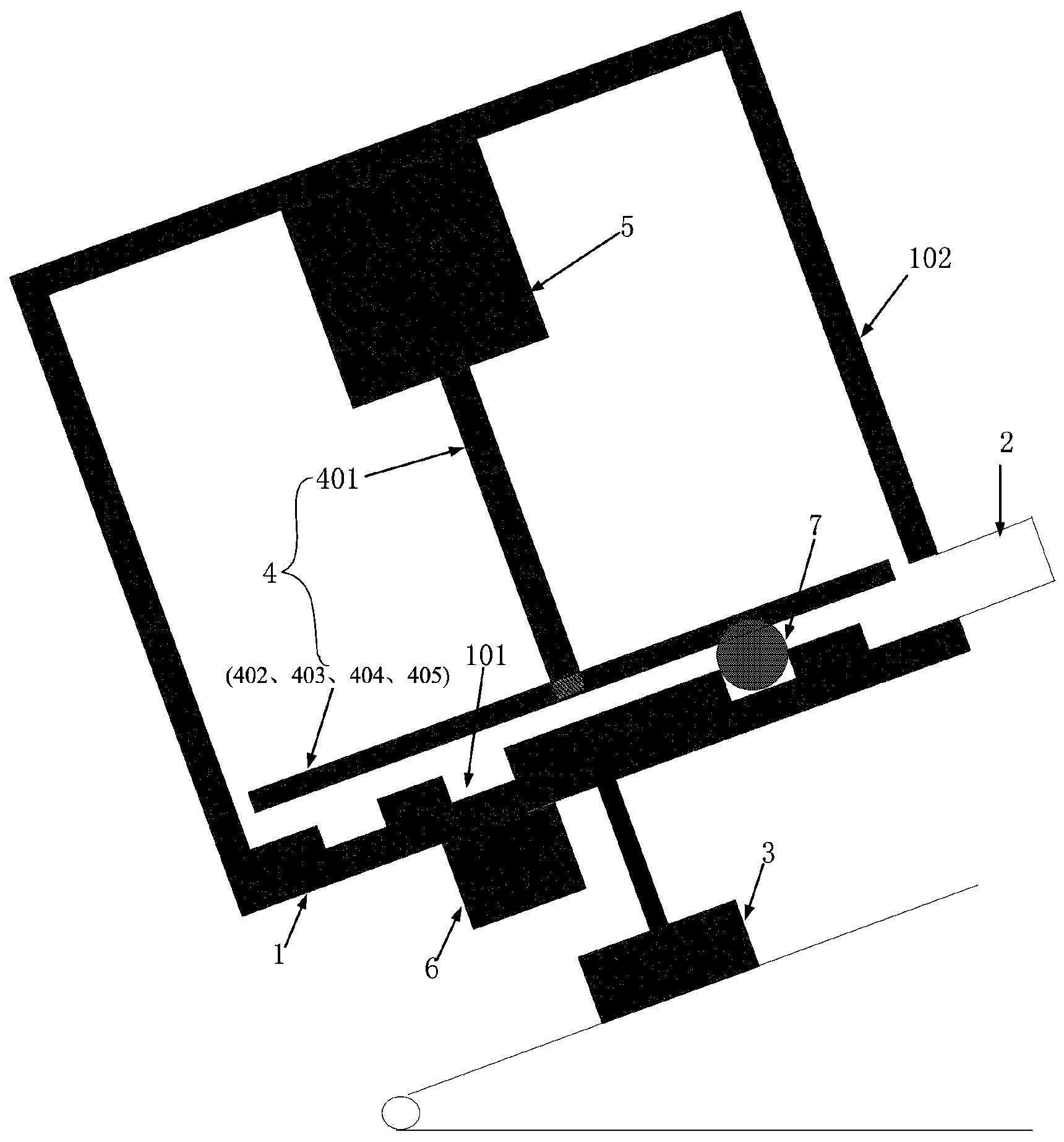
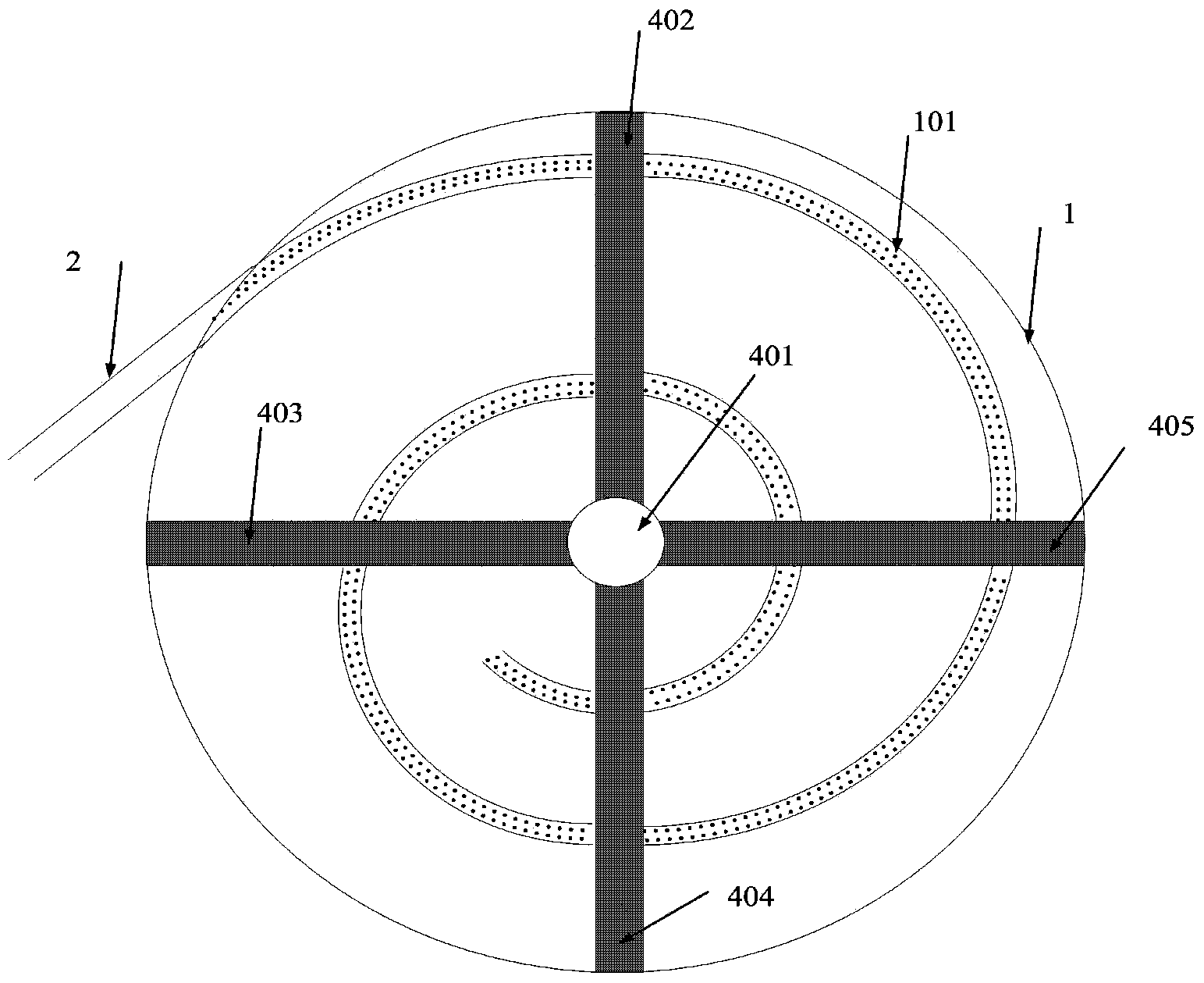
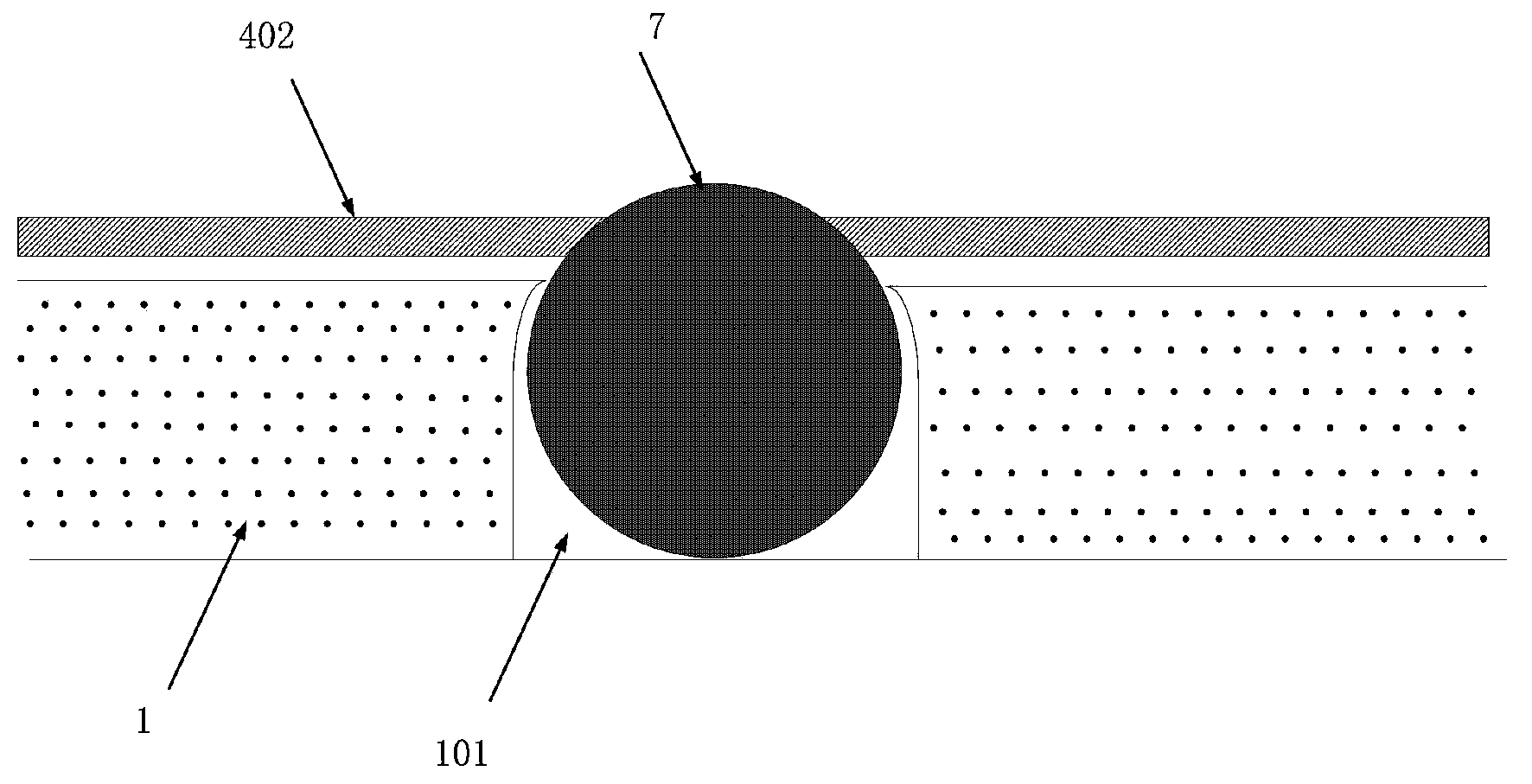
[0033] Such as figure 1 As shown, according to a preferred embodiment of the present invention, a centrifugal acceleration launching device driven by a motor includes: a circular wheel 1, an outer wall 102, a launch conduit 2, a launch angle adjustment base 3, a rotating drive part 4, The motor 5 and the filling device 6, the launch angle adjustment base 3 is wedged into the bottom of the fixed wheel 1 for adjusting the launch angle, wherein:

[0034] The circular wheel 1 and the outer wall 102 are combined to form an integral support, which is connected with the launch conduit 2, the rotating drive part 4, the motor 5, and the filling device 6 to form a whole launch, and the fixed wheel 1 is used as the bottom surface of the support. The wheel 1 includes an involute groove 101 and the starting po...


PUM


Abstract

The invention provides a centrifugal acceleration emission device based on motor driving. The centrifugal acceleration emission device comprises a round wheel disc, an outer wall, an emission conduit, an emission angle adjusting base, a rotary driving part, a motor and a filling device, wherein the emission angle adjusting base is wedged into the bottom of the fixed wheel disc and is used for adjusting an emission angle; an integrated supporting piece fixed wheel disc is composed of the round wheel disc and the outer wall and is used as a bottom surface of a supporting piece; the round wheel disc comprises an involute groove and the starting point of the groove is not located at the circle center of the fixed wheel disc; the emission conduit is fixed at the outer part of the round wheel disc and is connected with an outlet position of a connection groove; the motor and the rotary driving part are connected with an upper wall of the outer wall; the lower surface of the rotary driving part and the plane of the round wheel disc are not contacted and a gap is formed between the lower surface of the rotary driving part and the plane of the round wheel disc; the rotary driving part comprises a middle shaft and at least one driving bracket; the middle shaft is used for transmitting rotary output of the motor to the driving bracket; the filling device is mounted right below the starting point of the groove and is used for filling round balls into the round wheel disc.

Description

technical field [0001] The present invention relates to the field of mechanical acceleration devices, in particular to centrifugal acceleration devices, and in particular to a novel centrifugal acceleration launching device driven by a motor. Background technique [0002] The current anti-terrorism and anti-riot situation is becoming increasingly severe, and a weapon device that can launch powerful firepower to suppress riots in a short period of time is needed. The emergence of the centrifugal launch mechanism has been able to guarantee national security to a certain extent. The rotating mechanism driven by the high-speed motor generates centrifugal force, accelerates the continuous supply, and generates continuous strike force. [0003] However, the traditional centrifugal launch technology has its own inevitable shortcomings. The motor drives the rotating wheel to rotate at a high speed. At this time, the exit position of the accelerated object is uncertain, and an extern...

Claims


Application Information

Patent Timeline
Patent Type & Authority Applications(China)
IPC IPC(8): F41F7/00
Inventor 郭健易德亮罗春陈永亮朱孟韬章伟胡楠仲露
Owner NANJING UNIV OF SCI & TECH
Why Eureka
Try Eureka