
Bridge deformation monitoring method and system based on laser measurement and 485 bus

A technology of deformation monitoring and laser measurement, which is applied in the direction of measuring devices, optical devices, instruments, etc., can solve the problems of large measurement errors, blurred ruler reading, and affecting accuracy, and achieve continuous automatic monitoring, good directionality, and high brightness. Effect

Inactive Publication Date: 2014-12-24
ZHEJIANG SCI RES INST OF TRANSPORT +2
View PDF2 Cites 4 Cited by
  • Summary
  • Abstract
  • Description
  • Claims
  • Application Information

AI Technical Summary

Problems solved by technology

The steel wire drawing method requires simple equipment and is easy to operate, but the pulling force of the steel wire is difficult to grasp. At the same time, the steel wire has certain elasticity and toughness, especially after being bent, it is not easy to straighten. In addition, the influence of the steel wire's own weight causes a large measurement error
The level method has a blind spot in the short-distance measurement, and in the long-span measurement, the reading scale of the general level is blurred, which affects the accuracy
Theodolite method can only measure the load deformation of the main girder, and cannot reflect the static load
The most important point is that neither of the latter two methods can achieve continuous automatic monitoring

Method used


Image

  • Bridge deformation monitoring method and system based on laser measurement and 485 bus
  • Bridge deformation monitoring method and system based on laser measurement and 485 bus
  • Bridge deformation monitoring method and system based on laser measurement and 485 bus

Examples


Embodiment Construction

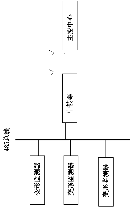
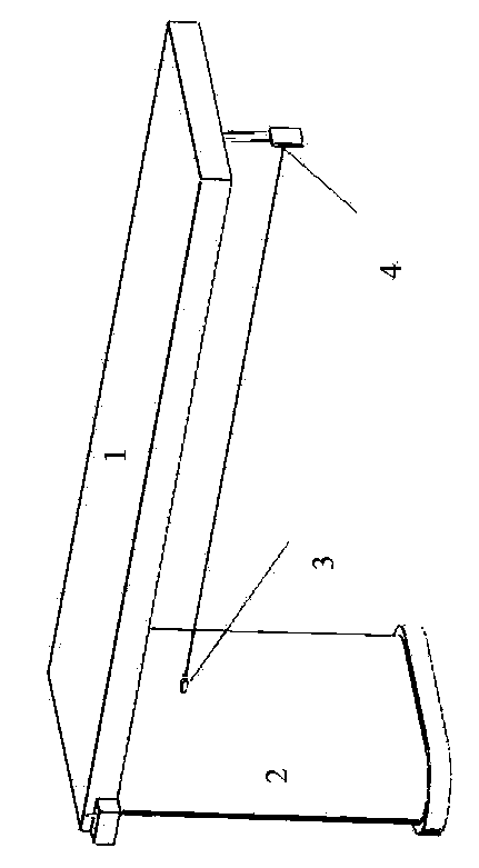
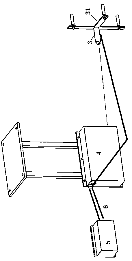
[0015] The bridge deformation monitoring system based on laser measurement and 485 bus in the present invention, the bridge deformation monitoring system is composed of several deformation monitors, relays, background main control center, such as figure 1 shown. The several deformation monitors are respectively arranged in each span to be measured of the whole bridge, and each deformation monitor is provided with a laser emitter and a laser receiving processor, and the laser receiving processor and the laser emitting device are passed through Power lead connection. The laser transmitter and laser receiving processor in each span constitute the acquisition unit in the span, and each acquisition unit is connected with the relay through the 485 bus by the laser receiving processor. The laser transmitter is installed and fixed on the bridge pier or other relatively fixed objects through a bracket; the laser receiving processor is installed and fixed under the bridge span that gen...


PUM


Abstract

The invention relates to a bridge deformation monitoring method and system based on laser measurement and a 485 bus and belongs to the technical field of structure deformation or displacement monitoring. Lasers are used as the basis for measuring the deformation of a bridge in the vertical direction, a laser receiving system is installed in the midspan of the bridge, the variation of the positions of the lasers on photosensitive elements after target imaging is converted to obtain information of downwarping of the midspan of the bridge, data of the detection result are transmitted to a forwarder through the 485 bus and the forwarder wirelessly transmits the data to a background master control center. The bridge deformation monitoring system is composed of a plurality of deformation monitors, the forwarder and the background master control center, wherein the deformation monitors are arranged in all the spans to be measured of the bridge; all laser receiving processors on the 485 bus work in a polling mode, and only one laser receiving processor responds to an instruction to output displacement byte data each time. Through the bridge deformation monitoring method and system based on laser measurement and the 485 bus, the downwarping conditions of all the spans of the bridge can be monitored continuously and automatically.

Description

technical field [0001] The invention relates to a structure deformation or displacement monitoring method and system thereof, in particular to a bridge deformation monitoring method and system based on laser measurement and 485 bus. Background technique [0002] At present, the main methods used in bridge deformation detection include steel wire drawing method, level method, theodolite method and so on. The steel wire drawing method requires simple equipment and is easy to operate, but it is difficult to control the pulling force of the steel wire. At the same time, the steel wire has certain elasticity and toughness, especially after being bent, it is not easy to straighten. In addition, the influence of the steel wire's own weight causes a large measurement error. The level method has a blind spot in the short-distance measurement, and in the long-span measurement, the reading scale of the general level is blurred, which affects the accuracy. The theodolite method can onl...

Claims


Application Information

Patent Timeline
Patent Type & Authority Applications(China)
IPC IPC(8): G01B11/16
Inventor 田浩金小平朱福民李万莉李方元
Owner ZHEJIANG SCI RES INST OF TRANSPORT
Learn More