AI technical title is built by Patsnap AI team. It summarizes the technical point description of the patent document.
A detection card and fan card technology, applied in the detection field, can solve the problems of insignificant heat dissipation effect, lack of heat generation area, cooling and other problems
Active Publication Date: 2014-12-24
MAIPU COMM TECH CO LTD
View PDF10 Cites 4 Cited by
Summary
Abstract
Description
Claims
Application Information
AI Technical Summary
This helps you quickly interpret patents by identifying the three key elements:
Problems solved by technology
Method used
Benefits of technology
Problems solved by technology
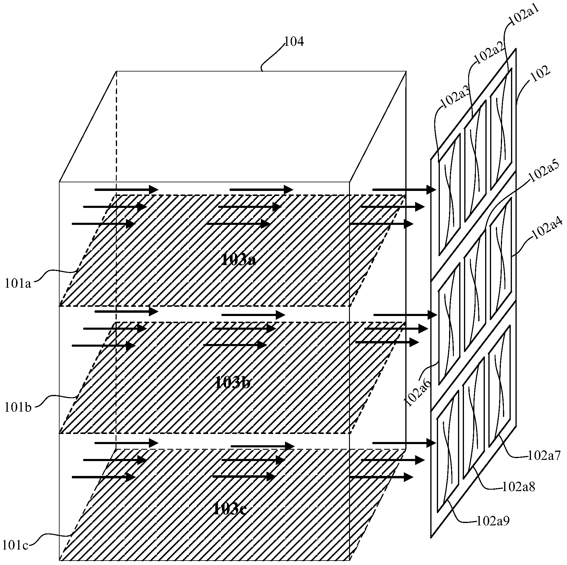
If the sockets 102b4, 102b5, and 102b6 of the fan card control circuit board 102e are mixedly inserted with fans corresponding to other layers, after the MCU 102d sends a speed regulation signal, the mixedly inserted fans will run at an accelerated speed, and the cooling effect on the middle layer is not obvious. The heat-generating area in the middle layer cannot be effectively cooled
Method used
Image
Click on the blue label to locate the original text in one second.
Reading with bidirectional positioning of images and text.
Examples
Embodiment 1
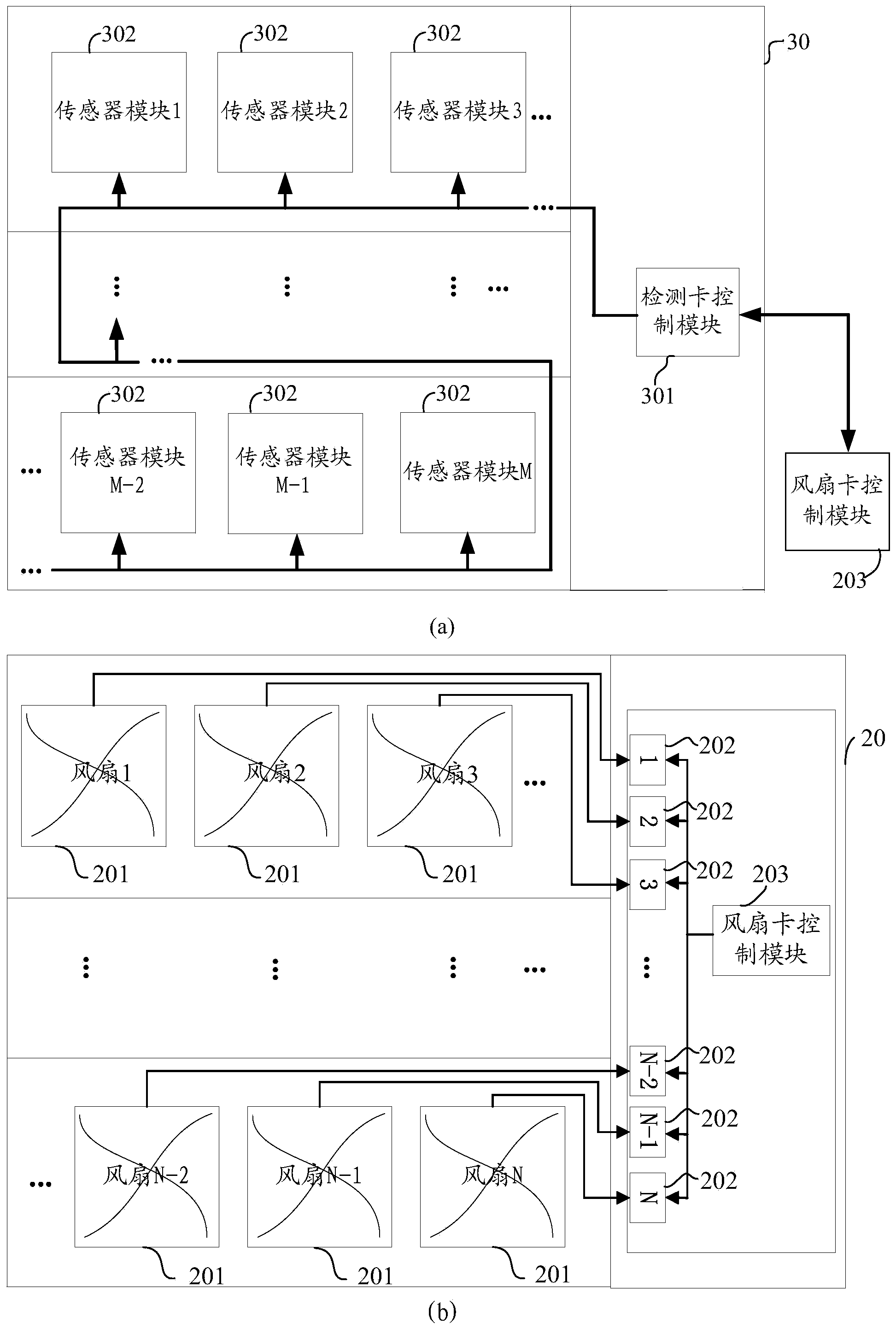
[0032] An embodiment of the present invention provides a detection card 30 for a fan card 20, specifically as image 3 (a) shown.
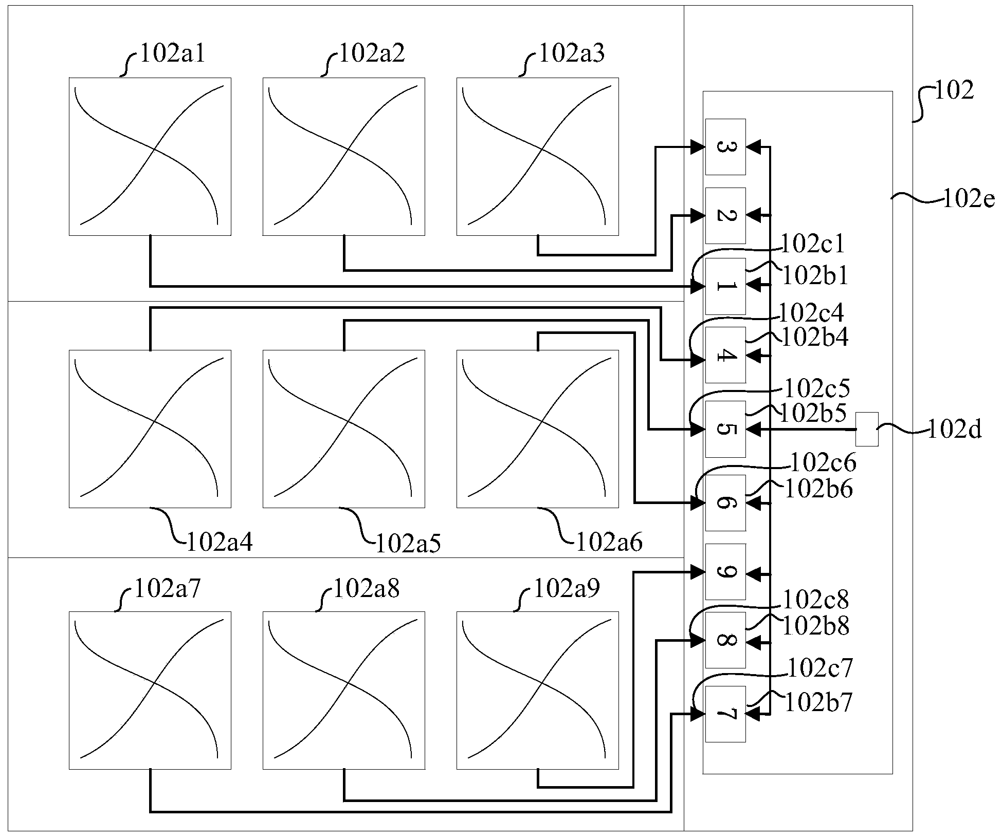
[0033] Among them, the fan card 20 such as image 3 As shown in (b), the fan card 20 is provided with: N fans 201; and N socket modules 202 that supply power to the N fans respectively; and are electrically connected with the N socket modules 202, respectively, for controlling the N socket modules 202 fan card control module 203.
[0035]The detection card control module 301 is electrically connected to the fan card control module 203 .
[0036] M sensor modules 302, the M sensor modules 302 are respectively electrically connected to the detection card control module 301, and the N sensor modules 302 in the M sensor modules 302 are respectively corresponding to the positions of the N fans 201 of the fan card, M≥ N, M, and N are all integers.
[0037] Wherein, the detection card control module 301 is used for...
Embodiment 2
[0092] An embodiment of the present invention provides a fan card detection system 90, specifically as Figure 9 As shown, it includes: a backplane 901 , the fan card 20 provided in the first embodiment, and the detection card 30 provided in the first embodiment. Wherein, the detection card 30 and the fan card 20 are arranged on the backplane in parallel and opposite to each other, and are connected through the backplanebus 902 .
[0093] It should be noted, Figure 9 In the fan card detection system 90 shown, the detection card 30 is located on the left side of the fan card 20 . Of course, those skilled in the art can easily understand that the detection card 30 can also be placed on the right side of the fan card 20 , which is not specifically limited in this embodiment of the present invention.
[0094] The detection system 90 of the fan card will be used below Figure 10 The detection card 30 shown is taken as an example, and the detection system 90 using the fan card ...
PUM
Abstract
The embodiment of the invention provides a detection card and a detection system of a fan card, so that an error that fans on the fan card are mixedly inserted to socket modules connected with the fans is detected. The detection card comprises a detection card control module and M sensor modules, wherein the detection card control module is electrically connected with a fan card control module, the M sensor modules are electrically connected with the detection card control module respectively, the N sensor modules in the M sensor modules correspond to N fans of the fan card respectively, the control card control module is used for sending a first instruction to the fan card control module, indicating the designated fans of the fan card to rotate at designated power, obtaining first detection numerical values of the M sensor modules respectively and determining that the designated fans are mixedly inserted to the socket modules connected with the designated fans if it is determined that the sensor modules with the first detection numerical values conforming to predetermined conditions do not correspond to the designated fans. The detection card and the detection system are applied to the field of detection techniques.
Description
technical field [0001] The invention relates to the technical field of detection, in particular to a detection card and a detection system for a fan card. Background technique [0002] High-power electrical equipment often generates a lot of heat during operation. If the heat is not dissipated in time, it will easily cause the electrical equipment to work at a high temperature. High temperature will not only make the operation of electrical equipment unstable, shorten the service life, and may even burn some parts. Therefore, it is often necessary to consider the heat dissipation of the electrical equipment when designing the electrical equipment. At present, a common heat dissipation method in electrical equipment is air-cooled heat dissipation, that is, a fan is used to blow or draw air to the heat-generating area to achieve the purpose of heat dissipation. [0003] Taking rack-mounted electrical equipment as an example, usually, the heating conditions of each heating ar...
Claims
Application Information
Patent Timeline
Application Date:The date an application was filed.
Publication Date:The date a patent or application was officially published.
First Publication Date:The earliest publication date of a patent with the same application number.
Issue Date:Publication date of the patent grant document.
PCT Entry Date:The Entry date of PCT National Phase.
Estimated Expiry Date:The statutory expiry date of a patent right according to the Patent Law, and it is the longest term of protection that the patent right can achieve without the termination of the patent right due to other reasons(Term extension factor has been taken into account ).
Invalid Date:Actual expiry date is based on effective date or publication date of legal transaction data of invalid patent.

