Grounding device

A grounding device and grounding clip technology, applied in electrical connection sockets and other directions, can solve problems such as casualties, loose connection points, equipment damage, etc., to ensure the safety of equipment and people, and it is not easy to be folded and damaged.

Inactive Publication Date: 2014-12-24
STATE GRID CORP OF CHINA +2
View PDF0 Cites 2 Cited by
  • Summary
  • Abstract
  • Description
  • Claims
  • Application Information

AI Technical Summary

Problems solved by technology

[0002] At present, the grounding device of the high-voltage short-circuit grounding wire used in the power supply, generation, and distribution systems is realized by using a temporary grounding clip made of metal with a copper nose. There is also a through hole in the concave part on the top, and then through the through hole on the copper nose and the through hole on the ground clip in turn through the bolt, the copper nose and the ground clip are locked, but there are some problems in this connection relationship: due to The lead wire connected to the copper nose is affected by external force (wind force) or manual operation, which will inevitably drive the copper nose to swing left and right and up and down. On the one hand, it will easily cause the concave part of the copper nose to be folded and damaged. On the other hand, when workers operate , When the equipment and lines are suddenly called, if the equipment and lines are in a short-circuit state, due to loose connection points and increased contact resistance, the large current caused by the sudden call cannot be quickly introduced into the ground, which will cause serious safety hazards such as equipment damage and casualties. as a result of

Method used


Image

  • Grounding device
  • Grounding device
  • Grounding device

Examples


Embodiment Construction

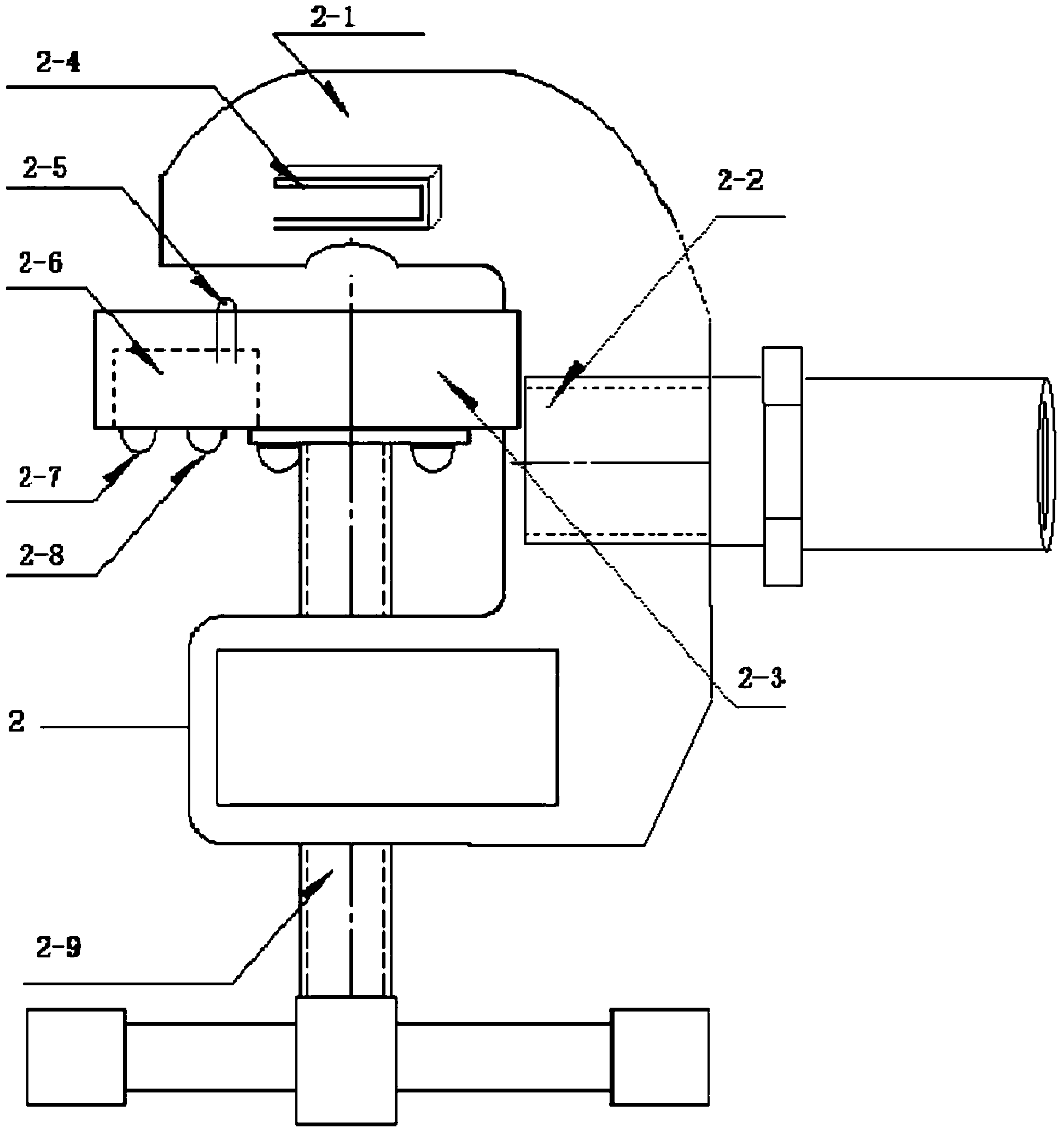
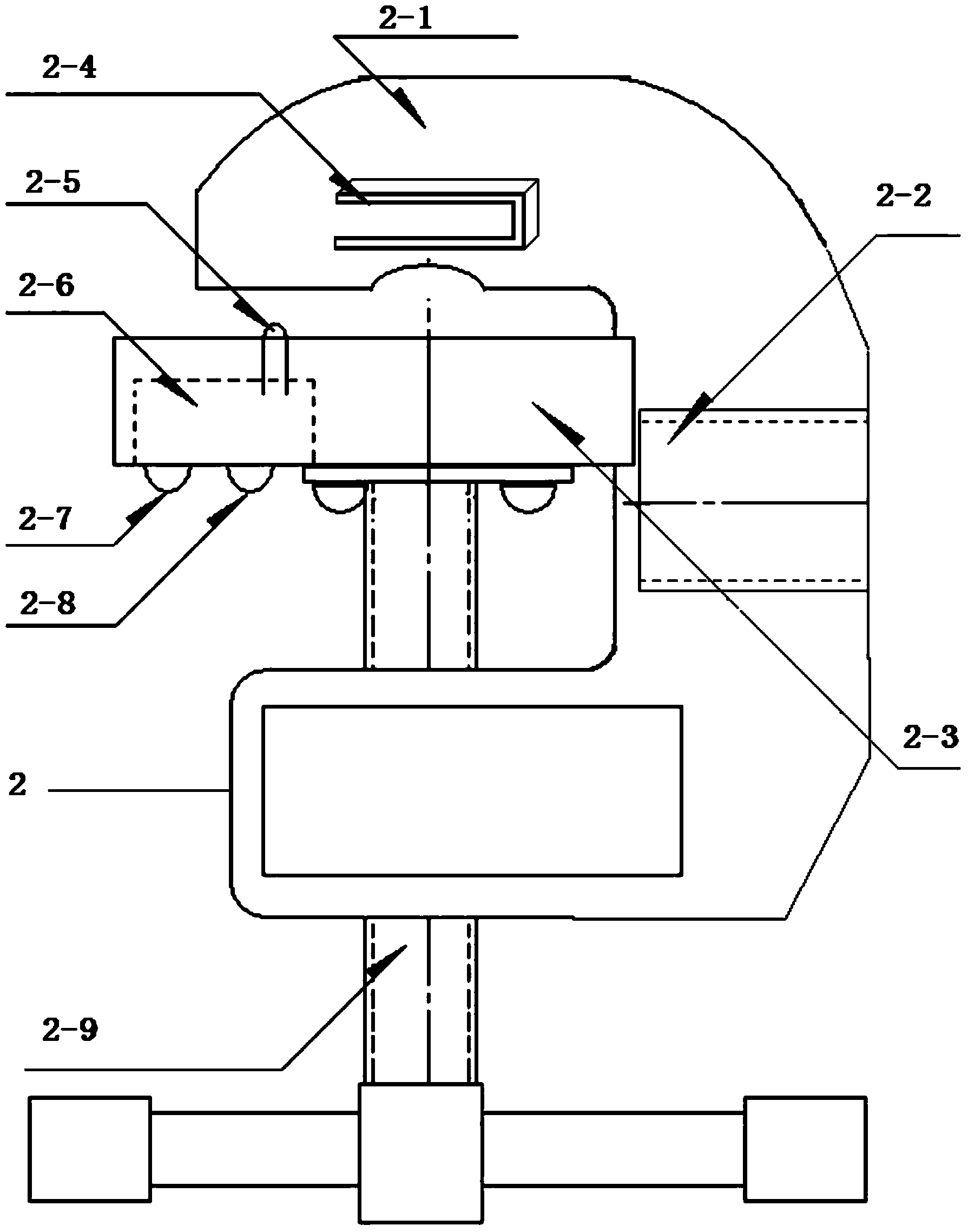
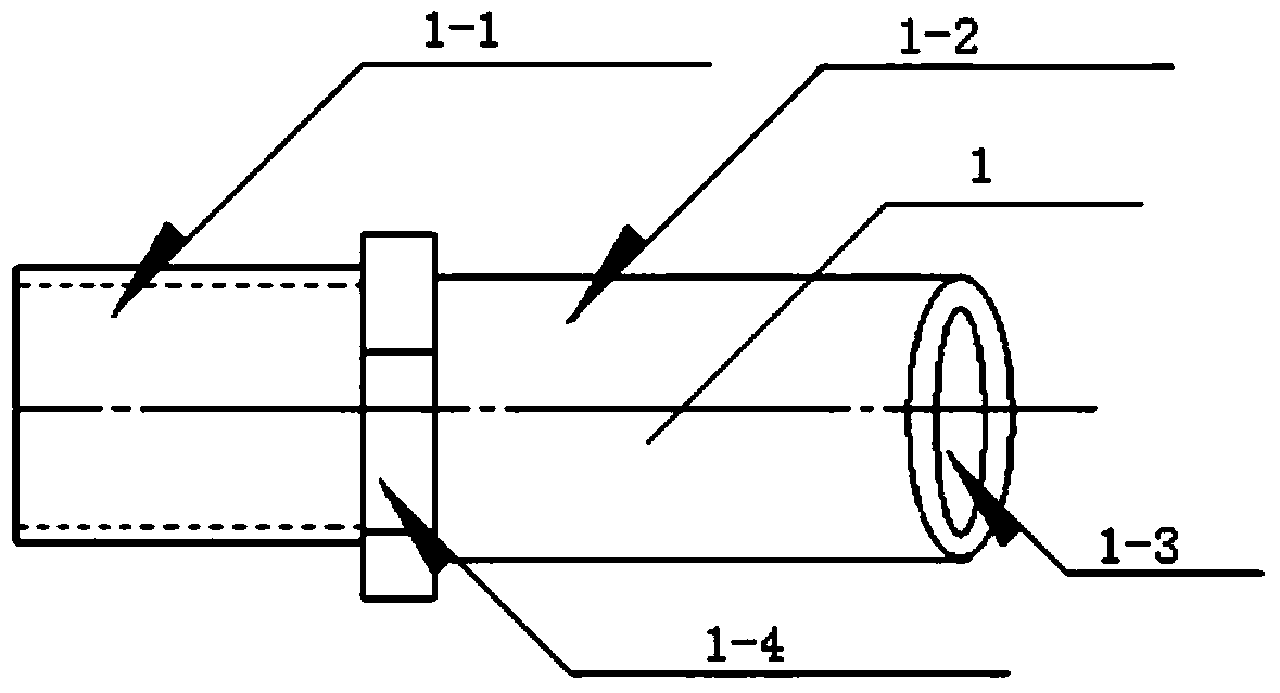
[0024] The present invention will be further described below in conjunction with accompanying drawing. Such as Figure 1-3 As shown, a grounding device is composed of a copper nose 1 and a grounding clamp 2. The copper nose 1 is composed of a crimping tube 1-2, a lead wire inlet 1-3 and a mounting piece 1-1. The grounding clamp 2 includes a support Frame 2-1, clamping part 2-3 and screw rod 2-9, one end of support frame 2-1 has the second threaded hole that matches with screw rod, and screw rod 2-9 passes through the second threaded hole, and screw rod 2- One end of 9 is connected with the clamping part 2-3, the other end of the screw (2-9) is connected with the operating handle, and the clamping part 2-3 moves in the groove of the support frame 2-1 driven by the screw 2-9 , the outer surface of the mounting part 1-1 is provided with threads, one end of the crimping tube 1-2 is connected to the mounting part 1-1, the other end of the crimping tube 1-2 is provided with a lead ...


PUM


Abstract

The invention discloses a grounding device. The grounding device is composed of a copper nose and a grounding clamp. The copper nose is composed of a compression connection pipe, a lead inlet and an installation part. The grounding clamp comprises a supporting frame, a clamping component and a screw. The outer surface of the installation part is provided with threads. One end of the compression connection pipe is connected with the installation part, and the other end of the compression connection pipe is provided with the lead inlet. A first threaded hole matched with the installation part is formed in the supporting frame. The grounding device has the advantages that the temporary grounding clamp is not prone to folding damage and poor connection, meanwhile, the effective energizing area is increased, requirements for grounding techniques of electric power according to rules are met, and accidents and personal injury caused by wrong grounding sequences are avoided.

Description

technical field [0001] The invention relates to a temporary grounding device for high and low voltage electrical circuits. Background technique [0002] At present, the grounding device of the high-voltage short-circuit grounding wire used in the power supply, generation, and distribution systems is realized by using a temporary grounding clip made of metal with a copper nose. There is also a through hole in the concave part on the top, and then through the through hole on the copper nose and the through hole on the ground clip in turn through the bolt, the copper nose and the ground clip are locked, but there are some problems in this connection relationship: due to The lead wire connected to the copper nose is affected by external force (wind force) or manual operation, which will inevitably drive the copper nose to swing left and right and up and down. On the one hand, it will easily cause the concave part of the copper nose to be folded and damaged. On the other hand, wh...

Claims


Application Information

Patent Timeline
IPC IPC(8): H01R11/26
Inventor 廖英祺官金兴周斌全姬俊鹏吴国梁程钢董骏许洪华王梁
Owner STATE GRID CORP OF CHINA
Why Eureka
Try Eureka