Method and mobile terminal for controlling rotary camera to rotate

A technology of rotating camera and mobile terminal, which is applied in the direction of use feedback control, image communication, color TV parts, etc. It can solve the problems of excessive heating of electric motors and idling of electric motors, and achieve the effect of avoiding idling

Active Publication Date: 2014-12-24
GUANGDONG OPPO MOBILE TELECOMM CORP LTD
View PDF5 Cites 26 Cited by
  • Summary
  • Abstract
  • Description
  • Claims
  • Application Information

AI Technical Summary

Problems solved by technology

[0006] Embodiments of the present invention provide a method for controlling the rotation of a rotating camera and a mobile terminal, aiming to solve the problem in the prior art that when the rotation of the rotating camera is controlled by a remote contr

Method used


Image

  • Method and mobile terminal for controlling rotary camera to rotate
  • Method and mobile terminal for controlling rotary camera to rotate
  • Method and mobile terminal for controlling rotary camera to rotate

Examples


Embodiment 1

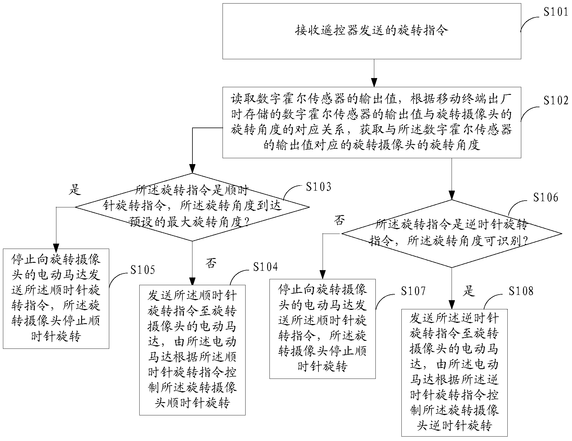
[0046] figure 1 It shows the implementation process of the method for controlling the rotation of the rotating camera provided by Embodiment 1 of the present invention. In this method, after the mobile terminal receives the rotation instruction sent by the remote control, it performs the rotation of the camera installed on the mobile terminal according to the instruction. control, as detailed below:

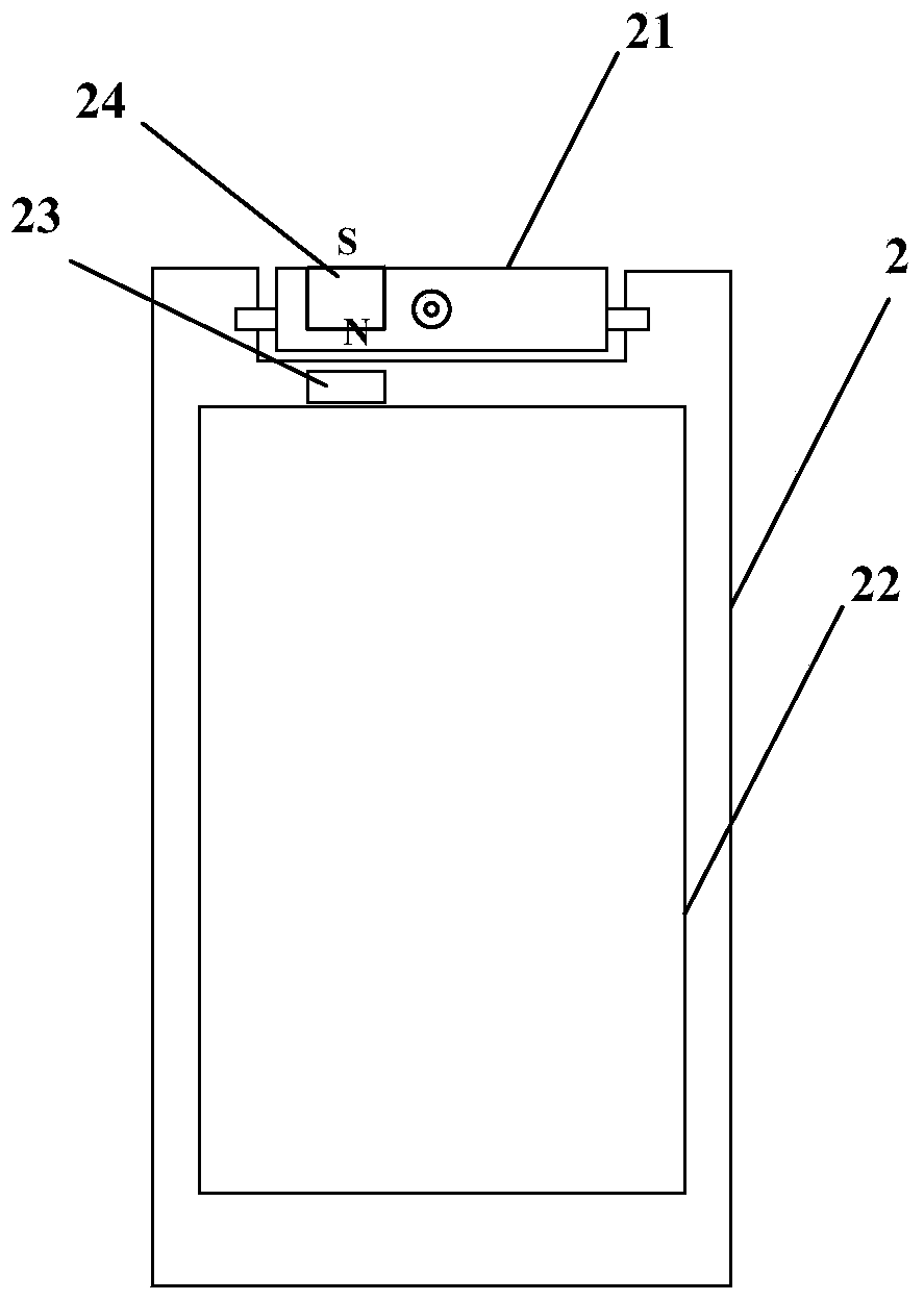
[0047] Wherein, a rotating camera 21 is installed on the mobile terminal 2, and an electric motor is built in the rotating camera 21. A digital Hall sensor 23 is installed on the main board 22 of the mobile terminal, and a magnet 24 is installed on one side of the rotating camera, as figure 2 As shown, after such installation, when the rotating camera rotates, there will be different distance values ​​between the magnet installed on the rotating camera and the digital Hall sensor installed on the main board of the mobile terminal, and the distance value can be determined by the ...

Embodiment 2

[0082] Figure 4 A specific structural block diagram of the device for controlling the rotation of the rotating camera provided by Embodiment 2 of the present invention is shown. For the convenience of description, only the parts related to the embodiment of the present invention are shown. The device for controlling the rotation of the rotating camera can be a software unit, a hardware unit or a combination of software and hardware built in the mobile terminal, the mobile terminal is equipped with a rotating camera, and an electric motor is built in the rotating camera, characterized in that A magnet is installed on one side of the rotating camera, and a digital Hall sensor is installed on the motherboard of the mobile terminal. The device 4 for controlling the rotation of the rotating camera includes: a rotation instruction receiving unit 41, a rotation angle obtaining unit 42, a first A rotation control unit 43 and a second rotation control unit 44 .

[0083] Wherein, the ...


PUM


Abstract

The invention belongs to the technical field of mobile terminals and provides a method and a mobile terminal for controlling a rotary camera to rotate. The method includes the steps that a rotation instruction sent by a remote control is received; an output valve of a digital Hall sensor is read, and the rotation angle of the rotary camera is obtained according to the corresponding relation of the output value of the digital Hall sensor and the rotation angle of the rotary camera; if the rotation instruction is a clockwise rotation instruction, and the rotation angle reaches the preset maximum rotation angle, sending of the clockwise rotation instruction to an electric motor of the rotary camera is stopped, and the rotary camera stops rotating clockwise; if the rotation instruction is a counterclockwise rotation instruction, and the rotation angle is unrecognizable, after the rotary camera is controlled to rotate counterclockwise to the maximum by 60 degrees according to the counterclockwise rotation instruction, sending of the counterclockwise rotation instruction to the electric motor of the rotary camera is stopped, and the rotary camera stops rotating counterclockwise. The phenomenon of idle running of the electric motor of the rotary camera is avoided.

Description

technical field [0001] The invention belongs to the technical field of mobile terminals, and in particular relates to a method for controlling the rotation of a rotating camera and a mobile terminal. Background technique [0002] Currently, rotating cameras have appeared on the market. There are two types of existing rotating cameras: one type of rotating camera has no motor, and the rotation angle of the rotating camera is controlled by the user through manual operation, which cannot accurately control the rotating angle of the rotating camera; the other type of rotating camera has a built-in electric motor, which can be controlled by Electric way to control the rotation angle of the rotating camera. [0003] However, at present, if the front and rear of the rotating camera are controlled by an electric motor, there will be the following disadvantages: because the initial angle of the rotating camera is not known, it is not known how much angle should be rotated to rotate ...

Claims


Application Information

Patent Timeline
IPC IPC(8): H04N5/232G05D3/12
Inventor 张强
Owner GUANGDONG OPPO MOBILE TELECOMM CORP LTD
Why Eureka
Try Eureka