Method and device for determining UE activation time

A technology of activation time and time, which is applied in the field of DTX and DRX, can solve the problems of short UE working time and affecting UE service quality, etc.

Active Publication Date: 2014-12-24
日照金慧科技信息咨询有限公司
View PDF8 Cites 30 Cited by
  • Summary
  • Abstract
  • Description
  • Claims
  • Application Information

AI Technical Summary

Problems solved by technology

[0005] In practice, however, the coexistence of these two discontinuity mechanisms can be problematic
from figure 1 It can be found that UE1 enters the DRX activation time and the base station has entered the DTX sleep time, etc., which leads to the UE working time may become very short, thus affecting the UE's quality of service (QoS: Quality of Service)

Method used


Image

  • Method and device for determining UE activation time
  • Method and device for determining UE activation time
  • Method and device for determining UE activation time

Examples


Embodiment 1

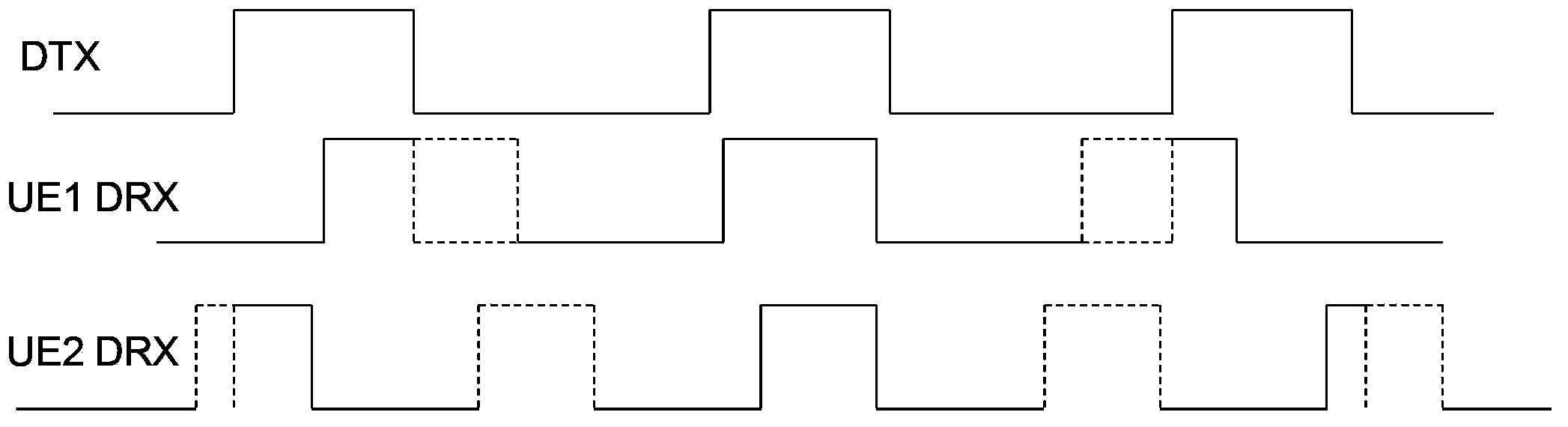
[0171] The following briefly describes the two mechanisms of DTX and DRX.

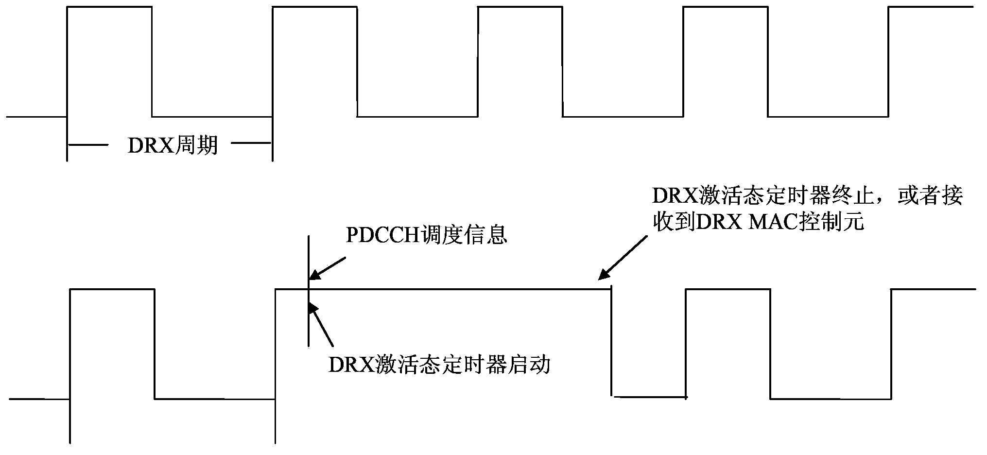
[0172] figure 2 It is a schematic diagram of DRX operation on the UE. The high level in the figure is the DRX activation time, that is, the UE is monitoring the PDCCH channel ( figure 2 DTX is not considered in the middle, so the UE activation time is equal to the DRX activation time), and the low level is the DRX sleep state. Specifically, at the initial stage of a DRX cycle, the UE first needs to start an onDurationTimer duration timer, and within the timer time, the UE needs to monitor the PDCCH channel to obtain scheduling information. If the UE does not receive scheduling information within the onDurationTimer timer, the UE enters a sleep state and stops monitoring the PDCCH channel to save power. When the above process repeats itself, a figure 2 The running graph of the first row in . If the UE receives the scheduling information within the onDurationTimer time, the UE needs to start anoth...

Embodiment 2

[0221] Figure 5 It is a schematic diagram of signaling in Embodiment 2 of the present invention. This embodiment is based on the first embodiment, and is a further refinement of the first embodiment in combination with specific scenarios. In this embodiment, the PDCCH command is taken as an example. The eNB (it can also be an S-eNB, namely Small eNB, which is not distinguished in the present invention) sends a PDCCH command to inform the UE that the DTX has been extended on the base station side, and the UE receives and detects After issuing the PDCCH order, the UE DTX can be adjusted accordingly in combination with some preset information. Specifically, this embodiment may include the following steps:

[0222] S501. The eNB sends signaling including DTX-RNTI configuration information to the UE, so as to configure the DTX-RNTI for the UE. This step is equivalent to a pre-processing step, and the DTX-RNTI is used to allow the UE to identify the PDCCH order carrying the DTX ...

Embodiment 3

[0241] Image 6 It is a flowchart of the third method of the present invention. This embodiment is similar to the first embodiment, but the difference in details is that in the first embodiment, the UE knows the DTX situation of the base station before extension, in other words, the UE has already learned a basic DTX as a basis. In this way, when the DTX of the base station is extended, it only needs to notify the UE of the extended information. to the next extended information. It can be said that the dynamics of this embodiment are relatively weak.

[0242] In this embodiment, when the base station has extended the DTX, the base station does not only send the extended information, but goes a step further, and directly notifies the DTX activation and sleep conditions in units of a single cycle by real-time or timing. UE, the UE determines the UE activation time completely according to the received DTX cycle and combined with its own DRX. When the UE needs to know the next...


PUM


Abstract

The embodiment of the invention discloses a method and device for determining UE activation time. The method comprises the steps that the extension information of base station DTX activation time is obtained, wherein the extension information is used for indicating extension on the base station DTX activation time of a base station; UE DTX activation time is adjusted according to the extension information, and the overlapped time of the UE DTX activation time and UEDRX activation time serves as UE activation time so that a PDCCH can be monitored, wherein the UE DTX activation time is the base station DTX activation time obtained by UE. When the base station changes original DTX of the base station to achieve UE QoS and other purposes, the modes such as base station DTX activation time extension information obtaining are adopted, the UE can obtain the latest DTX situation according to the change of base station side DTX, the correct UE activation time can be determined by combining UE DRX, and the QoS of the UE is finally ensured.

Description

technical field [0001] Embodiments of the present invention relate to the technical field of DTX and DRX, and in particular, to a method and device for determining UE activation time. Background technique [0002] At present, reducing power consumption and saving energy has become the general trend. On the one hand, for base stations, in traditional 2G and 3G networks, carriers of lower frequency bands are generally used to provide services for users. With the popularity of smart phones, users have put forward higher requirements for wireless transmission rates. The needs of users need to gradually use resource-rich high-band carriers to provide services. Due to the small coverage of high-band carriers, such base stations using high-frequency carriers are generally called small base stations, and the coverage of small base stations is called small base stations. Small Cell. In order to save power, 3GPP proposes to introduce a discontinuous transmission (DTX: Discontinuous ...

Claims


Application Information

Patent Timeline
Patent Type & Authority Applications(China)
IPC IPC(8): H04W52/02H04W76/04
CPCH04W52/0216H04W76/27H04W76/28Y02D30/70H04W72/21H04W72/23H04W28/0278
Inventor 常俊仁李亚娟冯淑兰
Owner 日照金慧科技信息咨询有限公司
Why Eureka
Try Eureka