Eureka AIR delivers breakthrough ideas for toughest innovation challenges, trusted by R&D personnel around the world.

Carrier structure for an armrest of a vehicle

A supporting structure and vehicle technology, applied to the special position of the vehicle, handrails, vehicle parts, etc., can solve the problems of heavy weight and high manufacturing cost

Active Publication Date: 2014-12-24
AUDI AG
View PDF7 Cites 0 Cited by
  • Summary
  • Abstract
  • Description
  • Claims
  • Application Information

AI Technical Summary

Problems solved by technology

However, the disadvantage is the high weight and high manufacturing costs of such a support structure 23

Method used


Image

  • Carrier structure for an armrest of a vehicle
  • Carrier structure for an armrest of a vehicle
  • Carrier structure for an armrest of a vehicle

Examples


Embodiment Construction

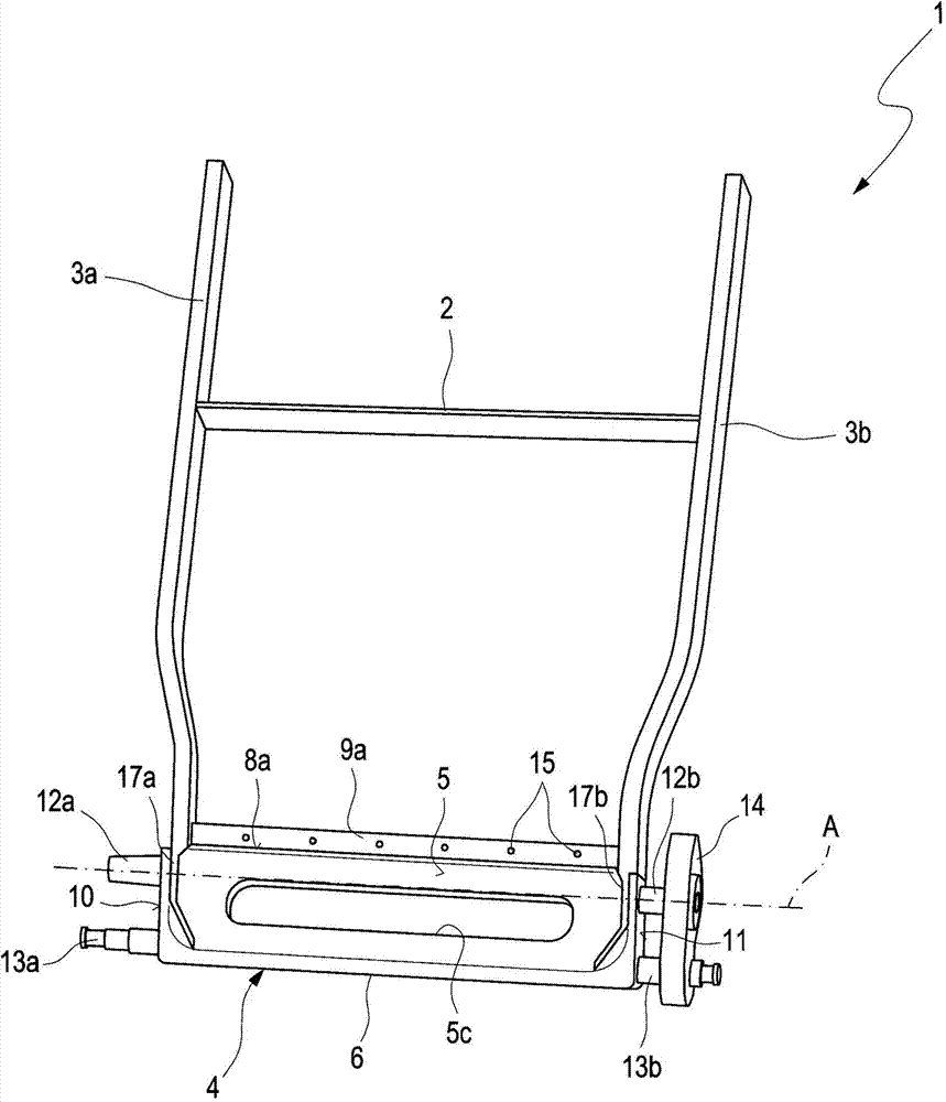
[0027] According to the basis of the present invention figure 1 The support structure 1 is used to receive the armrest body (not shown) that is used to form the vehicle armrest that can swing. Also connected by crossbar 2. The crossbeam 4 is articulated pivotally about a pivot axis A to a frame (not shown) of the vehicle via two pivot bearings 12a and 12b. Two further clamping levers 13 a and 13 b are likewise formed on the cross member 4 , wherein the clamping lever 13 b is operatively connected to the crash rocker 14 in order to prevent an uncontrolled upward pivoting of the armrest at high vehicle accelerations. Such a crash pendulum is known to those skilled in the art, and thus will not be described in detail here.

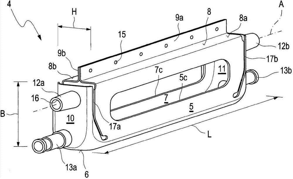
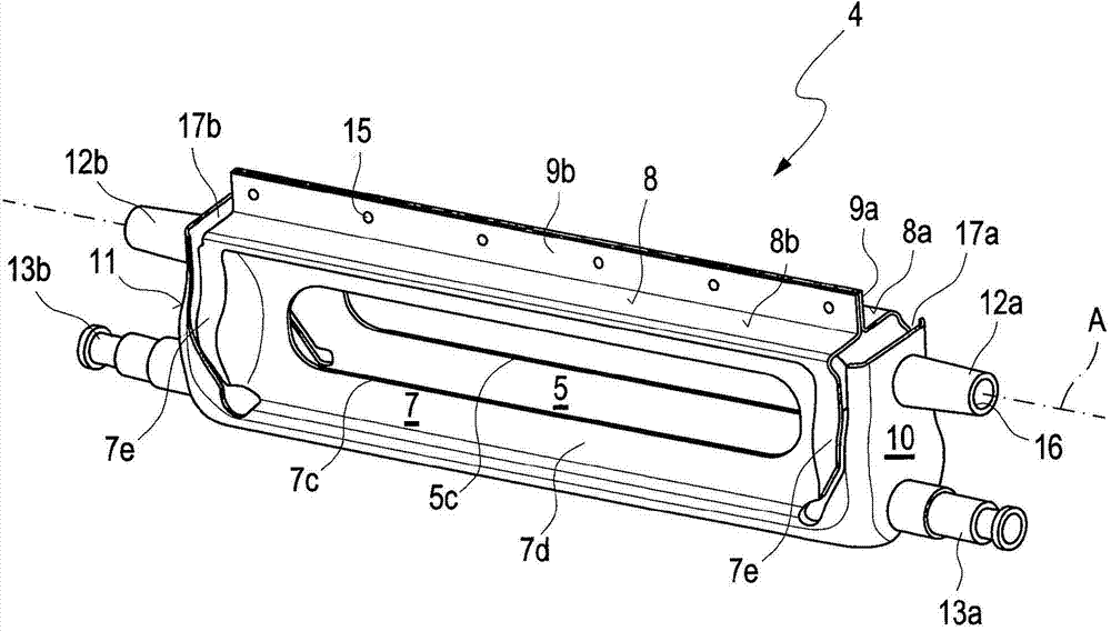
[0028] figure 2 , 3 4 and 4 show the beam 4 in different perspectives, wherein the cuboid shape of the beam can be seen. The cuboid cross member 4 is produced from a flat steel sheet, which is essentially designed as a cuboid-shaped development of the ...


PUM


Abstract

The invention relates to a carrier structure (1) for an armrest for pivotable articulation to a mount in a vehicle, said carrier structure having two carrier arms (3a, 3b) bearing a seat base, wherein the carrier arms (3a, 3b) are connected at one end to a cross member (4), and said cross member (4) has pins (12a, 12b) for pivotable seating in the mount, wherein according to the invention the cross member (4) is produced by tube-forming, bending and punching of a steel sheet corresponding substantially to the developed view of the cross member, wherein the pins are formed on the cross members as tube parts.

Description

technical field [0001] The invention relates to a bearing structure for an armrest pivotally articulated on a frame of a vehicle according to the preamble of claim 1 . Background technique [0002] In a pivotable center armrest of a vehicle, in particular a motor vehicle, the bracket body, which serves as a cushion for placing the passenger's forearm, is supported by a support arm of a support structure which is pivotably articulated on a frame of the vehicle . [0003] exist Figure 9 Such a support structure 23 for a center armrest 20 , which is hinged to a bracket 30 of a rear seat of a motor vehicle, is shown in a bottom view of the center armrest 20 . This support structure 23 comprises a crossbeam 24 consisting of a rectangular frame consisting of two solid round bars 24a and 24b extending parallel to the pivot axis A, the ends of which are connected by means of connections 27a and 24b. 27b connects and transitions to the two support arms 23a and 23b. In the middle ...

Claims


Application Information

Patent Timeline
Patent Type & Authority Applications(China)
IPC IPC(8): B60N2/46B21D22/26B21D53/88B60N2/75
CPCB21D53/88B60N2/753
Inventor S·曼戈尔德
Owner AUDI AG
Why Eureka
Eureka Blog
Learn More