A Laser Arc Hybrid Welding Method for Amorphous Alloy

A technology of amorphous alloy and laser arc, applied in laser welding equipment, welding equipment, welding/welding/cutting items, etc. Production and other issues, to achieve the effect of small thermal deformation, maintain metal structure and mechanical properties, and facilitate welding

Active Publication Date: 2016-04-06
DONGGUAN PROMETAL TECH CO LTD
View PDF5 Cites 0 Cited by
  • Summary
  • Abstract
  • Description
  • Claims
  • Application Information

AI Technical Summary

Problems solved by technology

[0003] In the prior art, when welding amorphous alloys, due to the unreasonable welding method, the crystallization of amorphous alloys often occurs, which makes it difficult to promote the application of amorphous alloys in depth
[0004] Because it is difficult to realize the tapping process on amorphous alloy materials, it is difficult to realize the structure of bolts and nuts on amorphous alloy products. Moreover, if adhesives are used to bond bolts and nuts to amorphous products, the connection strength does not meet the needs of production

Method used


Image

  • A Laser Arc Hybrid Welding Method for Amorphous Alloy
  • A Laser Arc Hybrid Welding Method for Amorphous Alloy
  • A Laser Arc Hybrid Welding Method for Amorphous Alloy

Examples


Embodiment 1

[0044] In this embodiment, the welding base material is a zirconium-based amorphous alloy Zr-Cu-Ni-Al-Nb, and the welding workpiece 1 is a zirconium workpiece, wherein the welding workpiece 1 in this embodiment is a zirconium bolt.

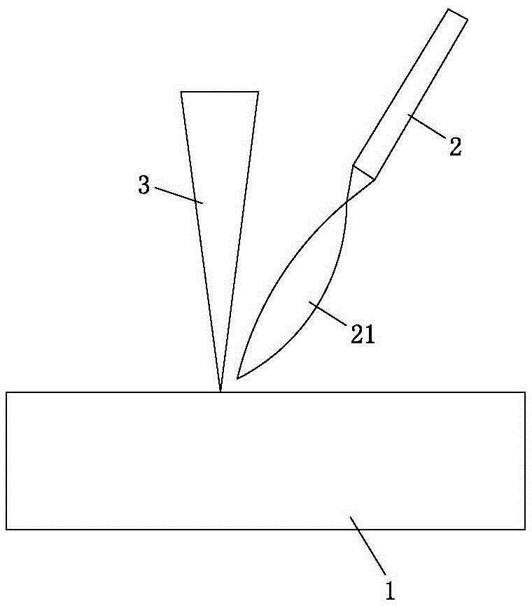
[0045] See figure 1 . A laser arc hybrid welding method for an amorphous alloy in this embodiment, the welding method is that the electrode 2 and the laser beam 3 are arranged in a paraxial composite manner, that is, the electrode 2 and the laser beam 3 are arranged on different axes, and the electrode 2 and the laser beam 3 are arranged on different axes. The bundles 3 form an acute angle between them. In this embodiment, the angle between the electrode 2 and the laser beam 3 is 30 degrees. Wherein, in this embodiment, the electrode 2 is a hollow tungsten electrode. The arc 21 generated by the electrode 2 in this embodiment is a MIG arc.

Embodiment 2

[0047] In this embodiment, the welding base material is a zirconium-based amorphous alloy Zr-Cu-Ni-Al-Nb, and the welding workpiece 1 is a copper workpiece, wherein the welding workpiece 1 in this embodiment is a copper nut.

[0048] See figure 1 . A laser arc hybrid welding method for an amorphous alloy in this embodiment, the welding method is that the electrode 2 and the laser beam 3 are arranged in a paraxial composite manner, that is, the electrode 2 and the laser beam 3 are arranged on different axes, and the electrode 2 and the laser beam 3 are arranged on different axes. The bundles 3 form an acute angle between them. In this embodiment, the angle between the electrode 2 and the laser beam 3 is 45 degrees. Wherein, the arc 21 generated by the electrode 2 in this embodiment is a TIG arc.

Embodiment 3

[0050] In this embodiment, the welding base material is a zirconium-based amorphous alloy Zr-Cu-Ni-Al-Nb, and the welding workpiece 1 is a nickel workpiece.

[0051] See figure 1 . A laser arc hybrid welding method for an amorphous alloy in this embodiment, the welding method is that the electrode 2 and the laser beam 3 are arranged in a paraxial composite manner, that is, the electrode 2 and the laser beam 3 are arranged on different axes, and the electrode 2 and the laser beam 3 are arranged on different axes. The bundles 3 form an acute angle between them. In this embodiment, the angle between the electrode 2 and the laser beam 3 is 40 degrees. Wherein, the arc 21 generated by the electrode 2 in this embodiment is a plasma arc.


PUM

PropertyMeasurementUnit
tensile strengthaaaaaaaaaa

Abstract

The invention relates to the technical field of welding of amorphous alloys, in particular to a laser arc compound welding method for amorphous alloys. The method comprises the welding of base metal amorphous alloys and the welding of workpieces; firstly, the surfaces of the welded workpieces are heated above a melting point by using arc generated by electrodes to form a shallow-layer molten pool facilitating the absorption of laser energy; then, the amorphous alloys and the shallow-layer molten pool on the surfaces of the welded workpieces are respectively irradiated by using laser beams, so that the amorphous alloys reaches above the melting point to form a molten state, and the shallow-layer molten pool on the surfaces of the welded workpieces is further formed to a deep-layer molten pool; As the benchmark in TTT chart, the welded workpieces and the amorphous alloys are welded under the condition of not generating the crystallization reaction; and the welded workpieces contain one or more than two elements in elements of the amorphous alloys. The welding method solves the problem that the amorphous alloys are difficultly tapped, preferably realizes the joint of the amorphous alloys and the welded workpieces, and enables the strength of the welded positions to become high; and the welded amorphous alloys still maintain the amorphous structure.

Description

technical field [0001] The invention relates to the technical field of welding of amorphous alloys, in particular to a laser arc hybrid welding method for amorphous alloys. Background technique [0002] Amorphous alloys have been widely used in the fields of electronics, machinery, and chemicals because of their excellent properties in terms of strength, hardness, toughness, wear resistance, corrosion resistance, soft magnetism, and superconductivity. However, although the amorphous alloy has the above-mentioned excellent characteristics, it has the disadvantages of being difficult to process and weld, which greatly limits its application range. Therefore, the welding of amorphous alloys has become a technical difficulty in expanding the application of amorphous alloys. [0003] In the prior art, when welding amorphous alloys, due to unreasonable welding methods, crystallization of amorphous alloys often occurs, which makes it difficult to popularize and apply amorphous all...

Claims


Application Information

Patent Timeline
Patent Type & Authority Patents(China)
IPC IPC(8): B23K26/348
CPCB23K26/24B23K26/322B23K26/348B23K2103/08B23K2103/18
Inventor 李奉珪
Owner DONGGUAN PROMETAL TECH CO LTD
Why Eureka
Try Eureka