A resistance welding method for amorphous alloy
An amorphous alloy, resistance welding technology, applied in resistance welding equipment, welding equipment, metal processing equipment and other directions, can solve the problems that amorphous alloys are difficult to popularize and apply in depth, difficult to realize bolt and nut structure, and the connection strength cannot meet production. , to achieve a wide range of welding parameters selection, easy mechanization and automation, small thermal deformation effect
- Summary
- Abstract
- Description
- Claims
- Application Information
AI Technical Summary
Problems solved by technology
Method used
Image

Examples
Embodiment 1
[0045] In this embodiment, the welding base material is a zirconium-based amorphous alloy Zr-Cu-Ni-Al-Nb, and the welding workpiece 1 is a zirconium workpiece.
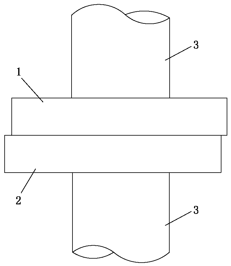
[0046] See figure 1 . In the resistance welding method of an amorphous alloy in this embodiment, the contact mode between the amorphous alloy and the welding workpiece is as follows: the amorphous alloy 1 is provided with a first plane, the welding workpiece 2 is provided with a second plane, and the amorphous alloy 1 is provided with a second plane. The first plane is in contact with the second plane of the welding workpiece 2 . Before welding, after the amorphous alloy 1 and the welding workpiece 2 are respectively connected to the electrode 3, the electrode 3 applies a pressure of 5 MPa and uses the resistance heat generated by the current to heat the amorphous alloy 1 and the welding workpiece 2 to above their respective melting points, and The TTT diagram is used as a reference, so that welder 2 and amorphous ...
Embodiment 2
[0048] In this embodiment, the welding base material is a zirconium-based amorphous alloy Zr-Cu-Ni-Al-Nb, and the welding workpiece 1 is a copper workpiece.
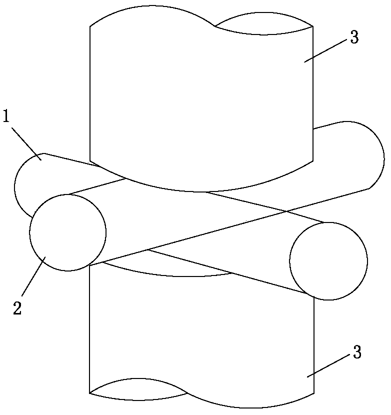
[0049] See figure 2. In the resistance welding method of an amorphous alloy in this embodiment, the contact mode of the amorphous alloy and the welding workpiece is as follows: the amorphous alloy 1 is provided with a first arc surface, the welding workpiece 2 is provided with a second arc surface, and the amorphous alloy 1 is provided with a second arc surface. The first arc surface of the crystal alloy 1 is in contact with the second arc surface of the welding workpiece 2 . Before welding, after the amorphous alloy 1 and the welding workpiece 2 are respectively connected to the electrode 3, the electrode 3 applies a pressure of 10 MPa and uses the resistance heat generated by the current to heat the amorphous alloy 1 and the welding workpiece 2 to their respective supercooled liquid phase regions , and based on the ...
Embodiment 3
[0051] In this embodiment, the welding base material is a zirconium-based amorphous alloy Zr-Cu-Ni-Al-Nb, and the welding workpiece 1 is a nickel workpiece.
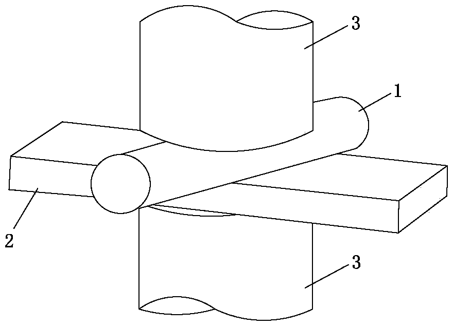
[0052] See image 3 . In the resistance welding method of an amorphous alloy in this embodiment, the contact mode of the amorphous alloy and the welding workpiece is as follows: the amorphous alloy 1 is provided with an arc surface, the welding workpiece 2 is provided with a plane, and the arc of the amorphous alloy 1 The surface is in contact with the plane of the welding workpiece 2. Before welding, after the amorphous alloy 1 and the welding workpiece 2 are respectively connected to the electrode 3, the electrode 3 applies a pressure of 0.1 MPa and uses the resistance heat generated by the current to heat the amorphous alloy 1 and the welding workpiece 2 to above their respective melting points, and Based on the TTT diagram, welder 2 and amorphous alloy 1 are welded without crystallization reaction.
PUM
 Abstract
Description
Claims
Application Information
 - R&D
- Intellectual Property
- Life Sciences
- Materials
- Tech Scout
- Unparalleled Data Quality
- Higher Quality Content
- 60% Fewer Hallucinations
Browse by: Latest US Patents, China's latest patents, Technical Efficacy Thesaurus, Application Domain, Technology Topic, Popular Technical Reports.
© 2025 PatSnap. All rights reserved.Legal|Privacy policy|Modern Slavery Act Transparency Statement|Sitemap|About US| Contact US: help@patsnap.com