
Sewing clamp plate for shirt collar

A sewing and plywood technology, which is applied to sewing equipment, sewing machine components, textiles and papermaking, etc., can solve the problems of cloth positioning and sewing that cannot achieve a high degree of uniformity, uneven workmanship, waste of production time, etc., to save labor costs, Facilitate raw edge cutting and reduce production cycle

Inactive Publication Date: 2015-01-07
JIANGSU HUAJIA SILK
View PDF6 Cites 4 Cited by
  • Summary
  • Abstract
  • Description
  • Claims
  • Application Information

AI Technical Summary

Problems solved by technology

[0002] The fabric structure of the collar and sleeves of the shirt is relatively special. In order to obtain a harder touch, it usually adopts a double-layer fabric structure. In the past, the sewing of these parts was relatively simple and backward, and it was usually necessary to use a template to draw lines on the fabric. Then fold the fabric along the marked line, then iron it to shape, cut the raw edge of the fabric, and finally stack the two cut fabrics for sewing to obtain a double-layer fabric, but this method is purely manual. For It is impossible to achieve a high degree of uniformity in the positioning and sewing of the fabric, and it also has high requirements for the manual skills of the operator. There are specific disadvantages: 1. Before the process is improved, it is necessary to manually draw the line according to the clean model to waste production time; 2. Drawing the line requires Providing highlighters, fading pens, chalk, etc. is a waste of cost; 3. According to ordinary workmanship requirements, it is easy to have asymmetrical shapes and uneven workmanship gestures, which cause quality problems; 4. To complete such processes, skilled workers with high technical content are required to complete operate

Method used


Image

  • Sewing clamp plate for shirt collar
  • Sewing clamp plate for shirt collar

Examples


Embodiment Construction

[0015] The preferred technical solutions of the present invention will be described in detail below in conjunction with the accompanying drawings.

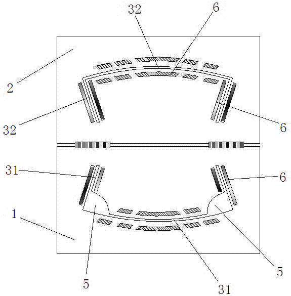
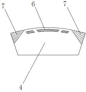
[0016] Such as figure 1 As shown, a sewing splint for a shirt collar of the present invention has an upper laminate 1 and a lower laminate 2, the same sides of the upper laminate 1 and the lower laminate 2 are hinged to each other, and the separating plate 4 is located between the upper laminate 1 and the lower laminate 2, The isolation board 4 can usually be disassembled, which is convenient for placing in the middle position. The upper laminate 1 has an upper stitch strip 31, and the lower laminate 2 has a lower stitch strip 32, and the upper stitch strip 31 and the lower stitch strip 32 have The relative position is aligned with each other after the upper laminate 1 and the lower laminate 2 are folded, and the outline shape of the separator 4 is set along the line shape of the upper needle strip 31 and the lower needle strip 32...


PUM


Abstract

The invention discloses a sewing clamp plate for a shirt collar. The sewing clamp plate comprises an upper-layer pressing plate and a lower-layer pressing plate, wherein the upper-layer pressing plate is provided with an upper-layer needle running strip, the lower-layer pressing plate is provided with a lower-layer needle running strip, relative positions of the upper-layer needle running strip and the lower-layer needle running strip are mutually aligned with each other and communicate with each other after the upper-layer pressing plate and the lower-layer pressing plate are folded, a partition plate is arranged between the upper-layer pressing plate and the lower-layer pressing plate, and the outline of the partition plate is arranged along the line shapes of the upper-layer needle running strip and the lower-layer needle running strip. Compared with the prior art, the sewing clamp plate for the shirt collar adopts the upper-layer pressing plate, the lower-layer pressing plate and the partition plate to clamping and fixing cloth for many times, so that a double-layer collar can be conveniently sewed in the upper-layer needle running strip and the lower-layer needle running strip by a sewing machine, the previous steps of scribing by a chalk and ironing for shaping before sewing can be omitted, operation is more convenient and rapid and rejection rate is reduced.

Description

technical field [0001] The invention relates to a sewing mold, in particular to a sewing splint of double-layer cloth for a shirt collar. Background technique [0002] The fabric structure of the collar and sleeves of the shirt is relatively special. In order to obtain a harder touch, it usually adopts a double-layer fabric structure. In the past, the sewing of these parts was relatively simple and backward, and it was usually necessary to use a template to draw lines on the fabric. Then fold the fabric along the marked line, then iron it to shape, cut the raw edge of the fabric, and finally stack the two cut fabrics for sewing to obtain a double-layer fabric, but this method is purely manual. For It is impossible to achieve a high degree of uniformity in the positioning and sewing of the fabric, and it also has high requirements for the manual skills of the operator. There are specific disadvantages: 1. Before the process is improved, it is necessary to manually draw ...

Claims


Application Information

Patent Timeline
Patent Type & Authority Applications(China)
IPC IPC(8): D05B35/00
CPCD05B35/00
Inventor 俞金键王春花计伟英
Owner JIANGSU HUAJIA SILK
Learn More