
Formwork for concrete structure pouring and pouring construction method

A construction method and concrete technology, applied in the direction of formwork/formwork/work frame, connection parts of formwork/formwork/work frame, building structure, etc., to achieve the effect of long turnover period, reducing human damage and saving construction cost

Active Publication Date: 2015-01-07
山东顺河路桥工程有限公司 +1
View PDF5 Cites 12 Cited by
  • Summary
  • Abstract
  • Description
  • Claims
  • Application Information

AI Technical Summary

Problems solved by technology

Both the pre-embedding process of drilling embedded parts and the perforation and fastening of pull bolts need to open holes through the wood formwork on the wood formwork, resulting in a decrease in the strength of the wood formwork, and the wood formwork itself has the disadvantages of easy deformation and large deformation. The fastening force directly acts on the wooden formwork. These factors not only lead to quality problems such as tympanum, grout leakage, and poor quality of embedded parts when pouring concrete, but also cause waste of formwork, which does not meet the requirements of energy conservation and environmental protection. It shortens the use turnover cycle of the formwork, increases the production cost, and prolongs the construction period

Method used


Image

  • Formwork for concrete structure pouring and pouring construction method
  • Formwork for concrete structure pouring and pouring construction method
  • Formwork for concrete structure pouring and pouring construction method

Examples


Embodiment Construction

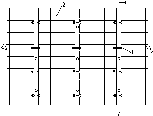
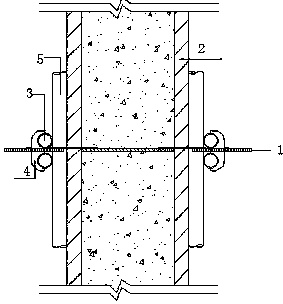
[0035] Such as Figure 1 to Figure 4 As shown, a formwork for pouring concrete structures includes two side forms, a tie mechanism 1 for tying the knot between the two side forms, and a vertical keel 5 and a transverse keel 3 placed outside each side formwork. Between the two side formworks is the concrete pouring area. Each side formwork comprises steel formwork 2 and square wood 6. The square wood has embedded parts piercing holes 7 and bolt holes 8 that both go through the square wood. The bolt holes are vertically arranged with the embedded parts piercing holes. The bolt holes correspond to the bolt holes on the two steel formworks adjacent to the wooden square. It is connected with two adjacent steel formworks by bolts. The tie mechanism includes a tie rod, a nut and a chevron 4. The tie rod includes a threaded section 9, a flat section 11, a steel bar section 10, a flat section and a threaded section connected in sequence. The length of the steel bar section is equal t...


PUM


Abstract

The invention provides a formwork for concrete structure pouring. The formwork comprises two side formworks, a tie mechanism, a vertical keel and a horizontal keel; the tie mechanism is used for performing tying between the two side formworks; the vertical keel and the horizontal keel are arranged on the outer sides of the two side formworks respectively; a concrete pouring area is formed between the two side formworks; each side formwork comprises steel templates and square timber; the square timber comprises a pre-embedded part penetrating hole and a bolt hole which penetrate the square timber; each bolt hole and the corresponding pre-embedded part penetrating hole are arranged vertically; each bolt hole is corresponding to bolt holes which are formed in the two steel templates which are adjacent to the corresponding square timber; each square timber is connected with the two adjacent steel templates through bolts; the tie mechanism comprises a pull rod, a nut and an inverted E-shaped part; the pull rod comprises a thread section, a flat section, a steel bar section, a flat section and the thread section which are connected in turn; the length of the steel bar section is equal to the thickness of the concrete pouring area; each flat section is arranged between the two corresponding adjacent steel templates and a gap value between the two steel templates is equal to the thickness of the flat section; the horizontal keel is limited in a groove of the inverted E-shaped part. The invention also provides a concrete structure pouring construction method.

Description

technical field [0001] The invention relates to a template for pouring concrete structures, and also relates to a construction method for pouring concrete structures. Background technique [0002] At present, the common construction method of reinforced concrete structures is to use wooden formwork for integral pouring construction. The specific method is: after the cushion concrete is poured, the steel bars are bound, and after the bottom plate and side wall steel bars are bound, the bottom plate, side wall wooden formwork support and Scaffolding is supported by piercing and fastening the pull bolts. The embedded parts are drilled and pre-embedded to complete the formwork reinforcement and the installation of the embedded parts. pouring. Both the pre-embedding process of drilling embedded parts and the perforation and fastening of pull bolts need to open holes through the wood formwork on the wood formwork, resulting in a decrease in the strength of the wood formwork, an...

Claims


Application Information

Patent Timeline
Patent Type & Authority Applications(China)
IPC IPC(8): E04G11/08E04G17/065E04B2/84
Inventor 刘兴宇李新璐程雷刘继顺曹振兴谢经凯徐盼程霞孟亚林王丽
Owner 山东顺河路桥工程有限公司
Learn More