Supercharge Your Innovation With Domain-Expert AI Agents!

Reversed bending preventing transmission chain

A transmission chain and anti-reverse technology, applied in the direction of transmission chains, chain links, etc., can solve problems such as instability and achieve the effect of improving stability

Active Publication Date: 2015-01-07
UNIVERSAL CHUANDONG TAIZHOU
View PDF6 Cites 9 Cited by
  • Summary
  • Abstract
  • Description
  • Claims
  • Application Information

AI Technical Summary

Problems solved by technology

This traditional transmission chain can bend freely in the forward and reverse directions, and is not stable during high-speed movement, so it is not suitable for precise transmission occasions

Method used


Image

  • Reversed bending preventing transmission chain
  • Reversed bending preventing transmission chain
  • Reversed bending preventing transmission chain

Examples


no. 1 example

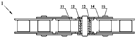
[0031] attached Figure 5-12 It is an anti-reverse bending transmission chain according to the present invention, which includes a left bending plate 21, a sleeve 22, a roller 23, a right bending plate 24, and a pin shaft 25; the left bending plate 21 and the right bending plate 24 are respectively It is in the shape of a horizontally stretched Z, and two parallel flat plates are connected together by the connecting plate 216, and the two parallel flat plates have the same width; the two vertical flat plates on the left curved plate 21 The one near the outside is the first flat plate, and the one near the inside is the second flat board. The center of the first flat board is provided with a first small hole 214, and the center of the second flat board is provided with a first large hole 215; Among the two vertical flat plates on the plate 24, the one close to the outside is the third flat plate, and the one close to the inside is the fourth flat plate. The center of the third ...

no. 2 example

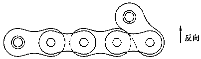
[0038] as attached Figure 13 , 14 As shown, the difference from the left curved plate and the right curved plate in the first embodiment is that the other end of the second flat plate of the left curved plate is set as a third anti-bending portion 213 parallel to the first anti-bending portion 211; The lower end of the third anti-bending portion 213 is provided with a rounded corner centered on the first large hole 215 .

[0039] The other end of the fourth flat plate of the right bending plate is set as a fourth anti-bending portion 245 parallel to the second anti-bending portion 241; the lower end of the fourth anti-bending portion 245 is provided with a second large hole 244 as the center rounded corners.

[0040] When working, the first anti-bending portion 211 and the third anti-bending portion 213 on the left bending plate can prevent reverse bending, and the second anti-bending portion 241 and the fourth anti-bending portion 245 on the right bending plate Both can p...


PUM


Abstract

The invention discloses a reversed bending preventing transmission chain. The reversed bending preventing transmission chain comprises a plurality of chain sections; each chain section comprises a left bending plate, a right bending plate, a sleeve and a roller; each left bending plate and each right bending plate are respectively transversely stretched like Z; two mutually-parallel flat plates are integrally connected through connecting plates; a first bending preventing part is arranged at the outer end part of each left bending plate, and the first bending preventing part is arranged in parallel with the connecting plate on each left bending plate; a second bending preventing part is arranged at the outer end part of each right bending plate, and the second bending preventing part is arranged in parallel with the connecting plate of each right bending plate; the first bending preventing parts and the second bending preventing parts are arranged in parallel; the left bending plates and the right bending plates are used in pairs; the adjacent chain sections are connected through hinge pins; in addition, the first bending preventing parts on the left bending plates at the rear chain section are contacted with the connecting plates on the left bending plates at the front chain section; third bending preventing parts on the right bending plates at the rear chain section are contacted with the connecting plates on the right bending plates at the front chain section. The reversed bending preventing transmission chain can be bent in one direction and is applicable to the accurate transmission place.

Description

technical field [0001] The invention relates to an improvement of a transmission chain, in particular to an anti-reverse bending transmission chain capable of preventing direction bending. Background technique [0002] like Figure 1-2 As shown, at present, the traditional chain 1 includes an inner chain link and an outer chain link. The inner chain link is composed of an inner chain plate 11, a first sleeve 12, and a first roller 13. The outer chain link is composed of an outer chain plate 14 and the first pin shaft 15, and both sides of the inner chain link and the outer chain link are arc-shaped; the inner chain link and the outer chain link are connected by the first sleeve 12 and the first pin shaft 15 with clearance fit , forming a living hinge. This traditional drive chain can bend freely in the forward and reverse directions, and is not stable during high-speed motion, so it is not suitable for precise transmission occasions. To this end, we have developed a revers...

Claims


Application Information

Patent Timeline
IPC IPC(8): F16G13/06
CPCF16G13/06F16G15/12
Inventor 黄伟达
Owner UNIVERSAL CHUANDONG TAIZHOU
Features
  • R&D
  • Intellectual Property
  • Life Sciences
  • Materials
  • Tech Scout
  • Unparalleled Data Quality
  • Higher Quality Content
  • 60% Fewer Hallucinations
Learn More