Pressure water storage barrel

A technology of pressure barrels and water storage barrels, which is applied to pressure vessels, fixed-capacity gas storage tanks, gas/liquid distribution and storage, etc. It can solve problems such as cumbersome and impractical operations, non-detachable water storage barrels, and poor safety, so as to reduce operations Process, save time, manpower and material resources, and improve safety

Inactive Publication Date: 2015-01-07
宁波重八净水科技有限公司
View PDF5 Cites 7 Cited by
  • Summary
  • Abstract
  • Description
  • Claims
  • Application Information

AI Technical Summary

Problems solved by technology

[0002] Existing pressure water storage barrels have two common structures. One is that the main body of the water storage barrel is divided into an upper half body and a lower half body, and an elastic interlayer is arranged between the upper half body and the lower half body. The barrel body and the lower half are welded. The upper part of the elastic partition is the water storage chamber, and the lower part is the air storage chamber. The water storage barrel of this structure cannot be disassembled, and the dirt cannot be disposed of after a period of use.
The other is that a water storage bag communicated with the water inlet and outlet is arranged inside the main body of the water storage bucket. It can be disassembled to clean the dirt, but after the disassembly and cleaning, the inside of the barrel must be re-injected with air pressure, which is cumbersome and impractical
[0003] In addition, both of the above two structures use the pressure barrel body as the wall of the gas storage chamber, which poses a great safety hazard. If the barrel body breaks or explodes, it will cause a greater threat and poor safety.

Method used


Image

  • Pressure water storage barrel
  • Pressure water storage barrel

Examples


Embodiment Construction

[0016] Below in conjunction with accompanying drawing and specific embodiment the invention is described in further detail:

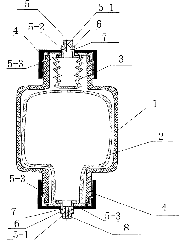
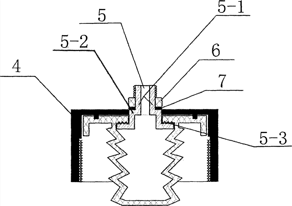
[0017] as attached figure 1 , 2 A pressure water storage barrel is shown, which includes a pressure barrel main body 1, an air storage bag 2 arranged inside the pressure barrel main body 1, and a water storage bag 3 arranged inside the pressure barrel main body 1, the top of the pressure barrel main body 1 and the The bottom is provided with a connecting nozzle 5, the pocket of the water storage bag 3 and the pocket of the air storage bag 2 communicate with the upper and lower connecting nozzles 5 respectively, and the connecting tube connected with the pocket of the water storage bag 3 The mouth 5 is the water inlet and outlet, and the connecting pipe mouth 5 communicated with the bag mouth of the air storage bag 2 is the air inlet and outlet, and the air valve core 8 is arranged on the air inlet and outlet. Valve core 8 plays the role of intake and ...


PUM


Abstract

The invention relates to the field of a water storage device about a water purifier, medical fire fighting, bathing, solar energy, a water pump, radiant floor heating, a boiler or a household appliance, and especially relates to a pressure water storage barrel, wherein the storage barrel comprises a pressure barrel body, and a reservoir bag and a water storage bag both which are arranged in the pressure barrel body, the top of the pressure barrel body and the bottom thereof are provided with a connecting nozzle, the water storage bag opening and the reservoir bag opening are respectively connected with upper and lower connecting nozzles, the connecting nozzle connected with the water storage bag opening is the water inlet and outlet, the connecting nozzle connected with the reservoir bag opening is the air inlet and outlet on which a valve core is arranged. When the device is disassembled for cleaning, the reservoir bag isn't affected, when the device is reassembled, air pressure cannot be again injected into the reservoir bag, thereby reducing operating processes, saving time and manpower and material resource, and greatly improving safety factor.

Description

technical field [0001] The invention relates to the fields of water purifiers, medical, fire-fighting, bathing, solar energy, water pumps, floor heating, boilers or water storage equipment in household equipment, in particular to a pressure water storage tank. Background technique [0002] Existing pressure water storage barrels have two common structures. One is that the main body of the water storage barrel is divided into an upper half body and a lower half body, and an elastic interlayer is arranged between the upper half body and the lower half body. The barrel body and the lower half are welded. The upper part of the elastic partition is the water storage chamber, and the lower part is the air storage chamber. The water storage barrel of this structure cannot be disassembled, and the dirt cannot be disposed of after a period of use. The other is that a water storage bag communicated with the water inlet and outlet is arranged inside the main body of the water storage b...

Claims


Application Information

Patent Timeline
Patent Type & Authority Applications(China)
IPC IPC(8): F16J12/00
CPCF16J12/00
Inventor 朱展宇
Owner 宁波重八净水科技有限公司
Why Eureka
Try Eureka