Dynamic test method for rail flaw detection

A dynamic test and rail technology, applied in the direction of using sonic/ultrasonic/infrasonic waves to analyze solids, can solve problems such as unfavorable installation of testing equipment, requirements for line length, inconvenient rail replacement, etc., and achieves small human constraints, complete and reliable functions. , light weight effect

Active Publication Date: 2015-01-07
ZHUZHOU TIMES ELECTRONICS TECH CO LTD +1
View PDF6 Cites 3 Cited by
  • Summary
  • Abstract
  • Description
  • Claims
  • Application Information

AI Technical Summary

Problems solved by technology

Its disadvantages are: it needs a dedicated line, there are requirements for the length of the line, it is inconvenient to replace the rail, and it does not use the integration in the laboratory
Its disadvantages are: the circular rail is quite different from the actual rail, and it is easily constrained by conditions.
Since the circular rail cannot be designed to be very large, it is impossible to have such a small curve radius rail in actual use. This damage setting method has a large gap with the actual damaged object detected, and it is not conducive to the installation of detection equipment.

Method used


Image

  • Dynamic test method for rail flaw detection
  • Dynamic test method for rail flaw detection
  • Dynamic test method for rail flaw detection

Examples


Embodiment 1

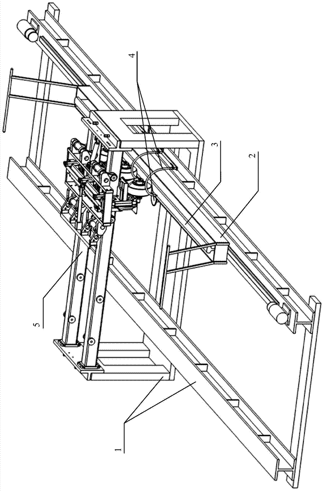
[0051] as attached figure 2 Shown, the specific embodiment based on the rail flaw detection dynamic test device of the inventive method comprises:

[0052] A support frame 1 for carrying a flaw detection device 5, and the flaw detection device 5 is arranged on the upper part of the support frame 1;

[0053] A sliding platform 2 is movably arranged on the bottom of the supporting frame 1 along the length direction of the supporting frame 1, and the sliding platform 2 is located below the flaw detection device 5;

[0054] The rail test block 3 arranged on the sliding platform 2, the rail test block 3 is located below the flaw detection device 5, and the rail test block 3 can be driven by the sliding platform 2 along the length direction of the support frame 1, and relative to the flaw detection device 5 Moving, the rail test block 3 is used to provide various damage simulations of the rail;

[0055] The auxiliary device 4 includes a coupling water injection device 42 , and th...

Embodiment 2

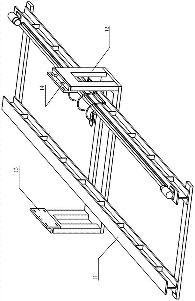
[0067] as attached Figure 10 Shown, the concrete embodiment of rail flaw detection dynamic test method of the present invention comprises the following steps:

[0068] A flaw detection device 5 is arranged on the top of the support frame 1;

[0069] A sliding platform 2 is movably arranged along the length direction at the bottom of the supporting frame 1, and the sliding platform 2 is located below the flaw detection device 5;

[0070] The rail test block 3 is set on the sliding platform 2, the rail test block 3 is located below the flaw detection device 5, and the rail test block 3 can be driven by the sliding platform 2 along the length direction of the support frame 1 and move relative to the flaw detection device 5 , the rail test block 3 is used to provide various damage simulations of the rail;

[0071] An auxiliary device 4 is provided on the supporting frame 1 , and the auxiliary device 4 includes a coupling water injection device 42 , which provides coupling water...

Embodiment 3

[0080] as attached Figure 12 , 13 , 14 and 15, the specific embodiment of the rail test block in the method of the present invention, the rail flaw detection test block is provided with a bolt hole saw kerf for simulating bolt hole cracks on the rail, and a rail waist for simulating the rail waist position defect. The rail test block 3 is formed by any one or several kinds of damages in the transverse hole, the rail head transverse hole for simulating the rail head defect, and the rail bottom sawing for simulating the rail bottom crack. The rail test block 3 described in the specific embodiment of the present invention can provide damage samples that are basically consistent with the dedicated line for simulating various rail damages in ultrasonic non-destructive testing, and comprehensively meet the needs of the actual situation of rail flaw detection.

[0081] The rail test block 3 includes a first test block 31, and the first test block 31 is provided with a bolt hole saw...


PUM

PropertyMeasurementUnit
Widthaaaaaaaaaa
Widthaaaaaaaaaa

Abstract

The invention discloses a dynamic test method for rail flaw detection. The dynamic test method comprises the following steps: a flaw detection device is arranged at the upper part of a supporting frame; a sliding platform is movably arranged at the bottom of the supporting frame in the length direction, wherein the sliding platform is located under the flaw detection device; a rail test block is arranged on the sliding platform, wherein the rail test block is located under the flaw detection device, can move opposite to the flaw detection device in the length direction of the supporting frame under the driving of the sliding platform, and is used for providing various damage simulations of a rail; an auxiliary device is arranged on the supporting frame, wherein the auxiliary device further comprises a coupling water spraying device that provides coupling water for a contact surface between the rail test block and a detection wheel of the flaw detection device. According to the invention, the dynamic test method for rail flaw detection can dynamically provide an all-around damage test environment for the rail flaw detection work, and is simple to operate, flexible in arrangement, small in environmental impact, and strong in adaptability.

Description

technical field [0001] The invention relates to the technical field of flaw detection, in particular to a rail flaw detection dynamic test method applied in the field of railway engineering. Background technique [0002] Ultrasonic flaw detection is the most widely used flaw detection method in the field of detection technology. The development and testing of non-destructive testing equipment are inseparable from the object to be tested. The main function of the ultrasonic rail flaw detection operation is to detect the damage of the rail itself, such as: nuclear damage at the rail head, vertical splitting, bolt hole cracks at the rail waist, crescent-shaped damage at the bottom of the rail, and various welding, fatigue, etc. resulting damage, etc. Therefore, how to provide these damage detection objects in a centralized, complete and comprehensive manner is an important part of ultrasonic nondestructive testing. There are many mold manufacturers in China that provide a var...

Claims


Application Information

Patent Timeline
IPC IPC(8): G01N29/04
Inventor 谭群林李红梁曹经纬夏浪王君罗江平邓亦农罗文胜廖时才
Owner ZHUZHOU TIMES ELECTRONICS TECH CO LTD
Why Eureka
Try Eureka