Content delivery network (CDN) quality monitoring method

A quality monitoring and monitoring machine technology, applied in data exchange networks, digital transmission systems, electrical components, etc., can solve the problems of highly uncontrollable, limited test coverage, and low test accuracy.

Active Publication Date: 2015-01-07
北京网宿科技有限公司
View PDF5 Cites 29 Cited by
  • Summary
  • Abstract
  • Description
  • Claims
  • Application Information

AI Technical Summary

Problems solved by technology

However, similar to the download rate test method, the page Poll test also depends on the tested terminal being a controllable and stable server, so it is highly dependent on the tested terminal being uncontrollable
[0012] Existing network quality tests are generally scattered because the IP library of the coverage test is relatively scattered, and the test method is single and depends on the IP address of the test object that can be controlled by itself (for example, the download rate test and the page poll test require the test object to be controllable). Impossible to test accurately if in an unfamiliar coverage area without your own server
At the same time, the IP address of the external client is tested, so there is a monitoring blind spot in the network situation closer to the CDN node
This has resulted in a situation where the test coverage is limited and the test accuracy is not high.
[0013] In addition, the existing CDN network tests can only directly see the final test results, such as the delay and packet loss rate of the test from device A to device B, the download rate, and the time spent on the poll page
In fact, there are often multiple switches or multiple network paths between A and B. From the test results from A to B, we can only know that there is a problem in the communication between A and B, but it is impossible to judge which specific network path the problem occurs in. link

Method used


Image

  • Content delivery network (CDN) quality monitoring method
  • Content delivery network (CDN) quality monitoring method
  • Content delivery network (CDN) quality monitoring method

Examples


Embodiment Construction

[0030] The detailed features and advantages of the present invention are described in detail below in the specific embodiments, the content of which is sufficient to enable any person skilled in the art to understand the technical content of the present invention and implement it accordingly, and according to the specification, claims and drawings disclosed in this specification , those skilled in the art can easily understand the related objects and advantages of the present invention.

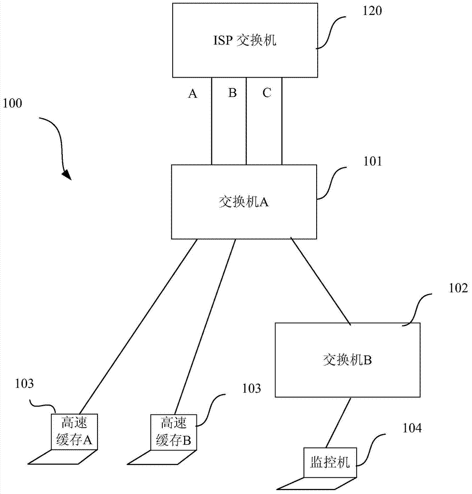
[0031] figure 1 A typical network topology framework of a data center is shown. The network topology framework of the data center 100 has a core switch 101 (such as switch A). The core switch 101 is interconnected with the switch 120 provided by the service provider (for example, an ISP switch) through one or more (3 shown in the figure) links. The core switch 101 can be connected to one or more downlink switches 102 (such as switch B). The node servers 103 (such as cache A and cache B) in...


PUM


Abstract

The invention relates to a content delivery network (CDN) quality monitoring method. A CDN comprises a data center, a bandwidth provider switch and edge nodes. The method includes the following steps that monitors in the data center carry out packet internet grope (PING) testing on node servers; the monitors in the data center carry out PING testing on the bandwidth provider switch networked with the data center; the monitors in the data center carry out testing on the edge nodes, if the edge nodes are controllable nodes, at least a part of PING testing, downloading rate testing and page Poll testing are carried out, and if the edge nodes are uncontrollable nodes, PING testing is carried out; the controllable nodes are edge nodes, capable of being logged into by a supervisor of the data center through the network and deploying downloading rate testing and page Poll testing, of HTTP website service, and the uncontrollable nodes are edge nodes, incapable of being logged into by the supervisor of the data center through the network or deploying downloading rate testing or page Poll testing, of the HTTP website service.

Description

technical field [0001] The invention relates to CDN network quality testing, in particular to a CDN network quality monitoring method. Background technique [0002] The full name of CDN is Content Delivery Network, that is, content distribution network. Its purpose is to publish the content of the website to the "edge" of the network closest to the user by adding a new layer of network architecture to the existing Internet, so that users can obtain the content they need nearby, and solve the Internet network congestion situation. Improve the response speed of users visiting the website. Technically, it fully solves the problem of slow response speed of users visiting websites caused by reasons such as small network bandwidth, large number of user visits, and uneven distribution of outlets. CDN is a distributed network established and covered on the bearer network and composed of service nodes distributed in different regions. It transmits the source content to the edge cl...

Claims


Application Information

Patent Timeline
Patent Type & Authority Applications(China)
IPC IPC(8): H04L12/26
Inventor 洪珂吴振永江宏
Owner 北京网宿科技有限公司
Why Eureka
Try Eureka