
Sideband filtering of directly modulated lasers with feedback loops in optical networks

a direct modulation and feedback loop technology, applied in the field of modulated laser sources in optical networks, can solve the problems of chirp, high cost of external modulated laser sources, and low chirp of modulated lasers, and achieve the effect of minimizing the chirp of dml-generated signals

Inactive Publication Date: 2006-08-10
CISCO TECH INC
View PDF26 Cites 28 Cited by
  • Summary
  • Abstract
  • Description
  • Claims
  • Application Information

AI Technical Summary

Benefits of technology

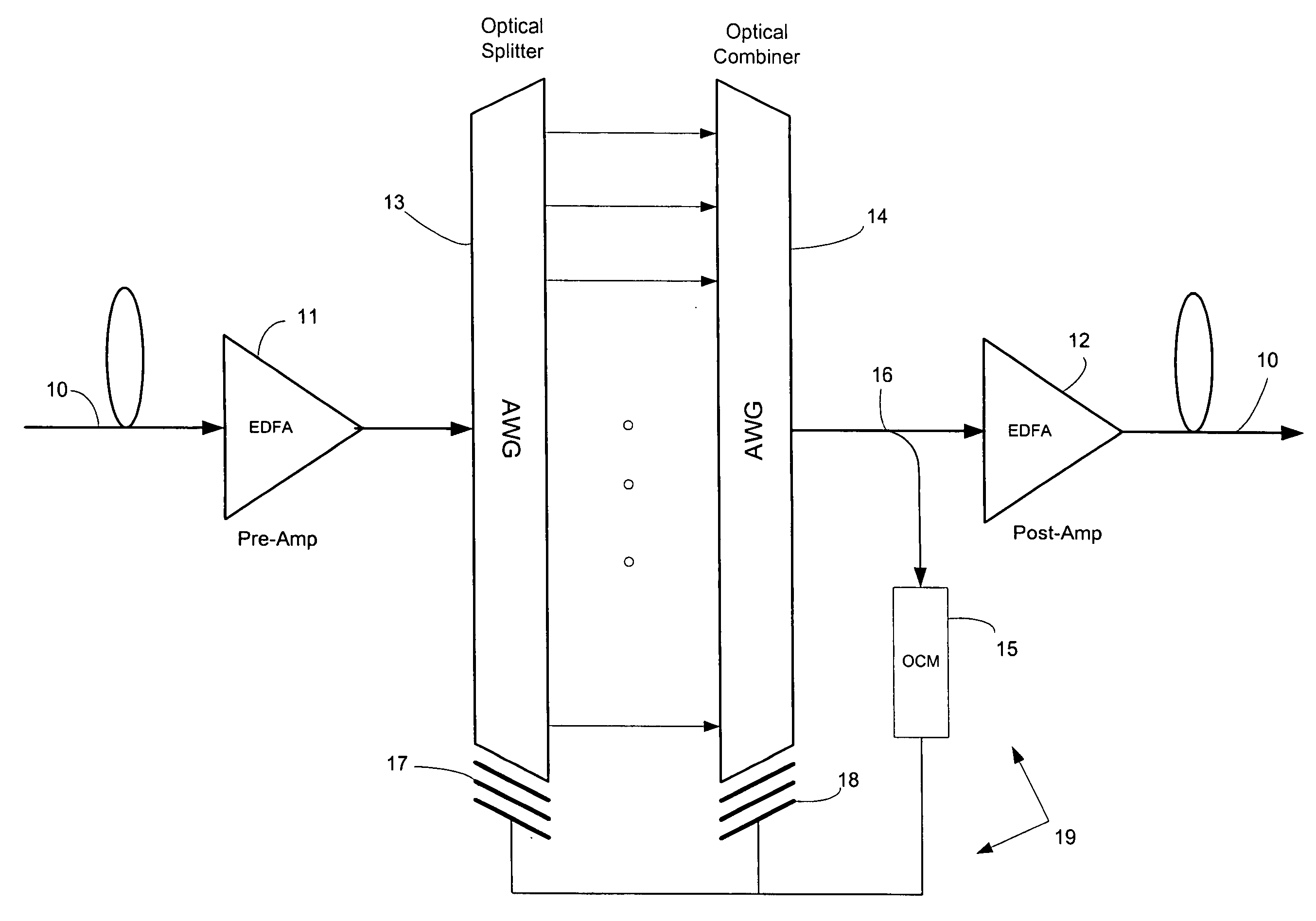
[0008] In a WDM optical network having at least one transmitter sending signals to at least one receiver over a network optical fiber, the present invention provides for a DML generating signals for the transmitter; a sideband filter between the transmitter and the receiver, the filtering characteristics of the sideband filter offset from a peak output of the DML compensating for chirp; a monitoring unit between the sideband filter and the receiver, the monitoring unit responsive to the sharpness of DML-generated signals filtered by the sideband filter; and a feedback loop from the monitoring unit for maintaining the offset between the DML and the sideband filter. Network components with filtering characteristics, such as AWGs (Arrayed WaveGuides), can be used as sideband filters. The sideband filter can also be located within the transmitter. Signals on the feedback loop from the monitoring unit, which can monitor the quality (the Q-factor or the BER) of the monitored signals, maintains the offset to minimize chirp of the DML-generated signals.

Problems solved by technology

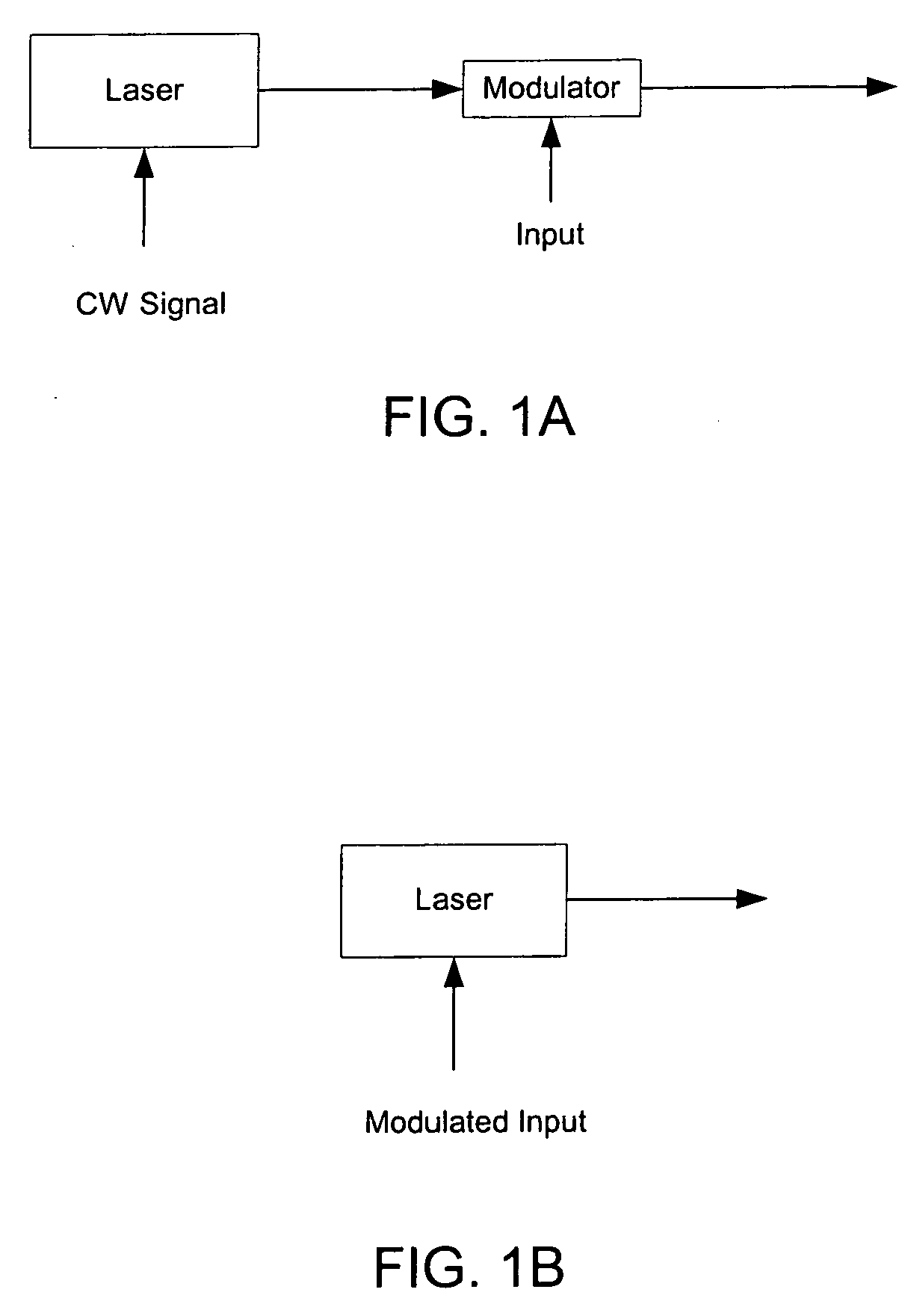
However, externally modulated laser sources are expensive and directly modulated lasers (DMLs), by which the semiconductor laser diode receives the input signal directly so that the laser diode's output is the light signal as illustrated in FIG. 1B, would seem desirable.
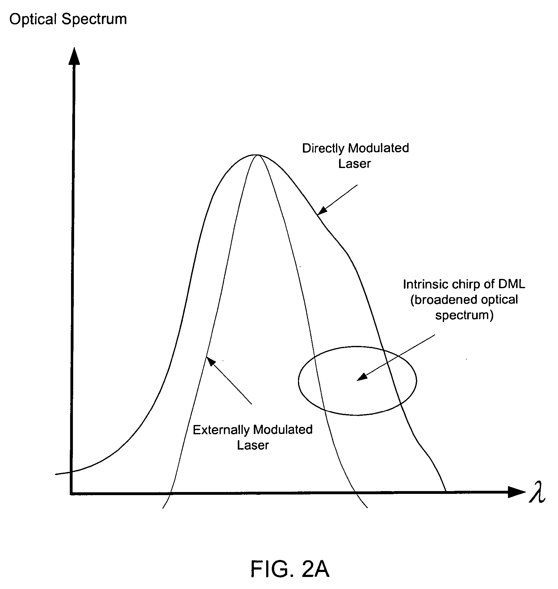
But directly modulated lasers (DMLs) face the well-documented problem of chirp, which is the reason that externally modulated lasers are typically preferred in optical networks.
This is undesirable, especially for WDM networks in which multiple optical signals having different wavelengths share an optical fiber, each wavelength defining a particular communication channel.
Additionally, increasing optical data rates, with signals at 10 Gb / s in commercial use expected in the near future, impose tighter restrictions on signal dispersion and render DMLs unsuitable as long distance signal sources.
Nonetheless, these modified lasers called ECL's (External Cavity Lasers) are expensive since the external reflectors must be precisely aligned and athermalized, and have not gained market acceptance.
A variation of the ECL approach of lowering chirp in DMLs with a fiber Bragg grating in place of a discrete grating also has met with little market acceptance.
Besides high cost, this approach leaves no room in the laser package for an onboard optical isolator and forces the isolator to be spliced onto the output fiber.
The electrical signal is “pre-emphasized” and the resulting output electrical signal at the receiver is “de-emphasized.” However, this approach can only compensate for a small amount of chirp and requires a specially matched receiver, which reduces interoperability of network components.
This requires an ASIC (Application Specific Integrated Circuit) be added between the receiver's pre-amplifier and clock data recovery (CDR) circuitry, which adds significant costs and power consumption.
There are limits to how much signal processing can be used to recover a chirped signal that is heavily dispersed.

Method used


Image

  • Sideband filtering of directly modulated lasers with feedback loops in optical networks
  • Sideband filtering of directly modulated lasers with feedback loops in optical networks
  • Sideband filtering of directly modulated lasers with feedback loops in optical networks

Examples


Embodiment Construction

[0016] The comparative outputs of externally modified lasers and DMLs are shown in FIG. 2A. It is evident that the output of the externally modulated laser has a much more narrow output bandwidth than the chirp-broadened output of the DML and is more suitable for WDM network signals than signals from a DML source.

[0017] However, recent research has pointed to a technique of narrowing DML output bandwidth by sideband filtering. The side lobes of the output spectrum are removed by a narrow optical passband filter offset from the fundamental frequency, i.e., peak output wavelength, of the DML output, or stated more precisely, the slope of the edge of the sideband filter chirps the signal oppositely from the chirp induced by the DML so that the two chirps cancel each other. As shown in FIG. 2B, the DML output for a 10 Gb / s input data signal marked by a solid line is filtered by a sideband filter as illustrated by a dotted line. While the sideband filter shown is Gaussian, almost any sh...


PUM


Abstract

In a WDM optical network DML signals are sideband filtered to compensate for chirp with a feedback loop carrying signals from a monitor unit which helps maintain the sideband filter offset from a peak output of the DMLs. Network components with filtering characteristics, such as AWGs, can be used as the sideband filters. The monitor units monitor the Q-factors or BERs of the filtered signals and the sideband offset is maintained by temperature control of the sideband filters with respect to the DMLs.

Description

BACKGROUND OF THE INVENTION [0001] The present invention is related to modulated laser sources for optical networks and, more specifically, to directly modulated lasers (DMLs) in optical networks. [0002] In an optical network the light signal sources are typically semiconductor lasers which are externally modulated, such as shown in FIG. 1A. In this arrangement a modulator, such as a electro-absorptive or Mach-Zehnder modulator, at the output of the semiconductor laser diode receives an input signal and modulates a constant (continuous wave) light signal from the laser diode. However, externally modulated laser sources are expensive and directly modulated lasers (DMLs), by which the semiconductor laser diode receives the input signal directly so that the laser diode's output is the light signal as illustrated in FIG. 1B, would seem desirable. DMLs can be approximately 75% cheaper than externally modulated sources, since the modulator and modulator driver are omitted. [0003] But dire...

Claims


Application Information

Patent Timeline
Patent Type & Authority Applications(United States)
IPC IPC(8): H04J14/02
CPCH04B10/504H04B10/58H04J14/02H04J14/0204H04J14/0212H04J14/0221H04J14/0227H04J14/0279H04J14/0246H04J14/02216H04J14/0305
Inventor PARASCHIS, LOUKASTHEODORAS, JAMES T. IIGERSTEL, ORNAN
Owner CISCO TECH INC
Learn More