Z-shaped steel sheet pile, and steel sheet pile wall formed from said Z-shaped steel sheet pile

A technology for steel sheet piles and joints, which is applied in sheet pile walls, buildings, and foundation structure engineering, etc. It can solve problems such as easy deformation of joints, easy rotation of Z-shaped steel sheet piles, and large joints, so that the weight of the steel will not increased effect

Inactive Publication Date: 2015-01-07
JFE STEEL CORP
View PDF8 Cites 2 Cited by
  • Summary
  • Abstract
  • Description
  • Claims
  • Application Information

AI Technical Summary

Problems solved by technology

[0021] On the other hand, since the shape of the Z-shaped steel sheet pile does not restrain the soil like the U-shaped steel sheet pile and the hat-shaped steel sheet pile, it is easy to drive the Z-shaped steel sheet pile due to ground resistance when driving. Rotation, etc. occur, so a large force is generated at the joint
As mentioned above, the Larsen-type joint part is relatively weak against tensile force and rotational force. On the other hand, its degree of freedom is low. Therefore, there is a problem that the joint part is easily deformed. more obvious
[0023] Even after the steel sheet piles are driven in, the steel sheet piles receive force from the foundation, especially in the event of an earthquake, etc., for Larsen joints that are relatively weak in tension and strong in restraint , there is a problem that it is easy to deform at the joint part
If the joint part is deformed, there will be a problem that the water-stopping effect will be reduced
[0024] As described above, there is a problem in the joint part of the Z-shaped steel sheet pile that force tends to act on the joint part during and after the driving of the steel sheet pile, so that the joint part tends to be deformed.
[0026] However, increasing the plate thickness is associated with an increase in the weight of the steel, and therefore, becomes less economical

Method used


Image

  • Z-shaped steel sheet pile, and steel sheet pile wall formed from said Z-shaped steel sheet pile
  • Z-shaped steel sheet pile, and steel sheet pile wall formed from said Z-shaped steel sheet pile
  • Z-shaped steel sheet pile, and steel sheet pile wall formed from said Z-shaped steel sheet pile

Examples


Embodiment Construction

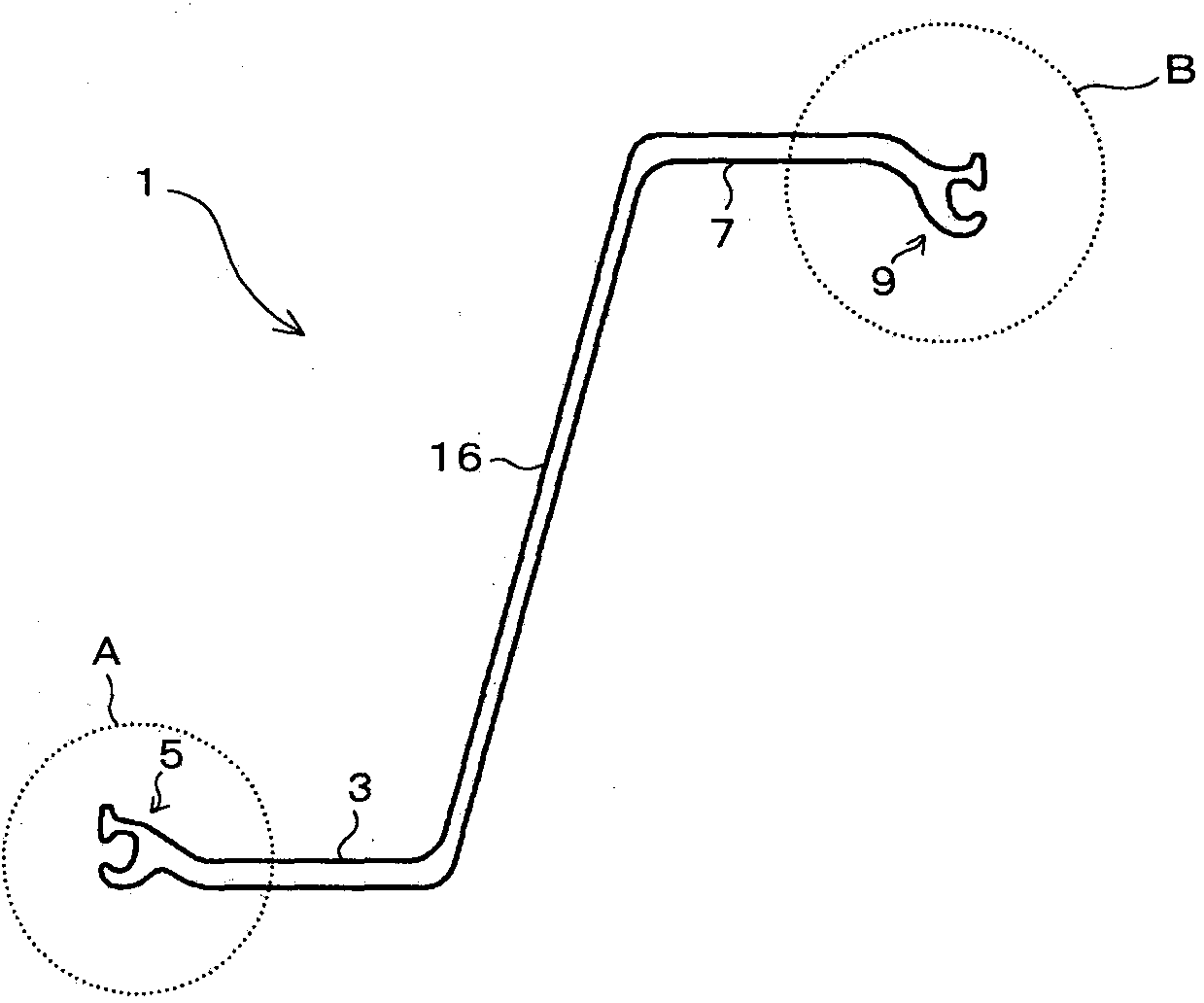
[0043] The Z-shaped steel sheet pile 1 which concerns on this embodiment is a Z-shaped steel sheet pile which has the 1st joint part 5 formed in the terminal end of the 1st flange part 3 which comprises the Z-shaped steel sheet pile 1, and the 2nd joint. The part 9 is formed at the end of the second flange part 7. By arranging the Z-shaped steel sheet piles 1 adjacent to each other and connecting the first joint part 5 and the second joint part 9 in an engaging manner, a steel plate can be formed. Pile wall 27 (refer to Figure 5 ).

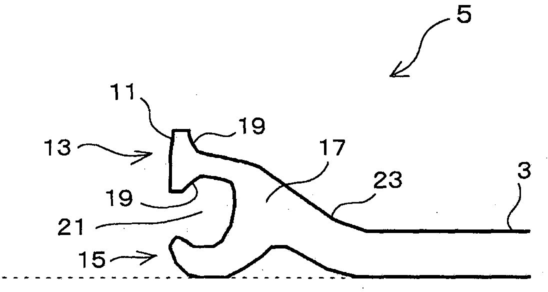
[0044]The first joint part 5 is a double-claw joint part having a main claw 13 and an auxiliary claw 15, wherein the main claw 13 has a bulging part 11 at the end and is arranged inside the steel sheet pile, and the auxiliary claw 15 is connected to the main claw. 13 are formed in an opposing manner and arranged outside the steel sheet piles.

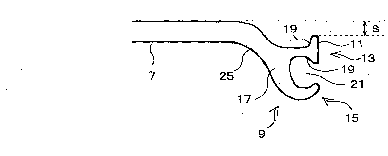
[0045] In addition, the second joint part 9 is a double-claw joint part having a main claw 13 and an ...


PUM


Abstract

This Z-shaped steel sheet pile (1) has: a first joint section (5) formed at the tip of a fist flange section (3) configuring the Z-shaped steel sheet pile (1); and a second joint section (9) formed at the tip of a second flange section (7). A steel sheet pile wall (27) can be formed by disposing Z-shaped steel sheet piles (1) adjacent to each other, and linking the first joint sections (5) and the second joint sections (9) by causing the engagement thereof. The Z-shaped steel sheet pile (1) is characterized by: the first joint section (5) being a double claw joint section having a primary claw (13), which has an expanded section (11) at the tip and is disposed at the inside of the steel sheet pile, and an auxiliary claw (15), which is formed in a manner so as to face the primary claw (13) and is disposed at the outside of the steel sheet pile; and the second joint section (9) being a double claw joint section having a primary claw (13), which has an expanded section (11) at the tip and is disposed at the outside of the steel sheet pile, and an auxiliary claw (15), which is formed in a manner so as to face the primary claw (13) and is disposed at the inside of the steel sheet pile.

Description

technical field [0001] The present invention relates to a Z-shaped steel sheet pile used for harbor and river revetment, a guard plate, and cofferdam construction in the civil engineering field, and a steel sheet pile wall formed of the Z-shaped steel sheet pile. [0002] In the present specification, the Z-shaped steel sheet pile refers to a steel sheet pile having a substantially Z-shaped overall shape in which flanges are formed at both ends of an obliquely arranged web (web) so as to be continuous with the web. Background technique [0003] U-shaped steel sheet piles, Z-shaped steel sheet piles, or hat-shaped steel sheet piles are generally used as steel sheet piles used in harbor and river revetment, guard plates, and cofferdam constructions in the civil engineering field. In addition, the linear steel sheet pile is mainly used in the steel sheet pile small house (cell) construction method. The said steel sheet pile is used as a steel wall by connecting joint parts. ...

Claims


Application Information

Patent Timeline
Patent Type & Authority Applications(China)
IPC IPC(8): E02D5/04
CPCE02D5/04
Inventor 宇佐美俊辅
Owner JFE STEEL CORP
Why Eureka
Try Eureka