

Pullers for zipper and article using puller
A technology of sliders and zippers, applied in the direction of application, sliding fastener components, fasteners, etc., can solve the problems of troublesome hook and pull tab joint operation, inability to quickly tighten and untie zippers, etc.
- Summary
- Abstract
- Description
- Claims
- Application Information
AI Technical Summary
Problems solved by technology
Method used
Image

Examples
no. 1 approach
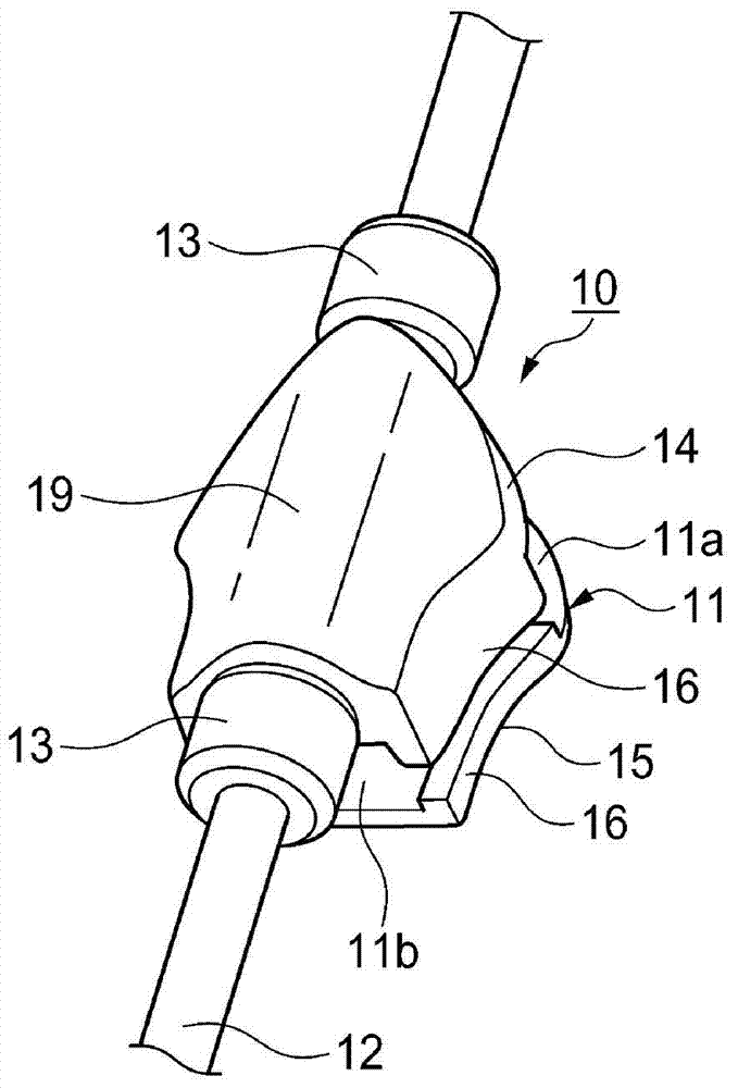
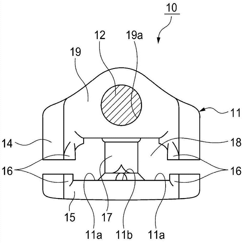
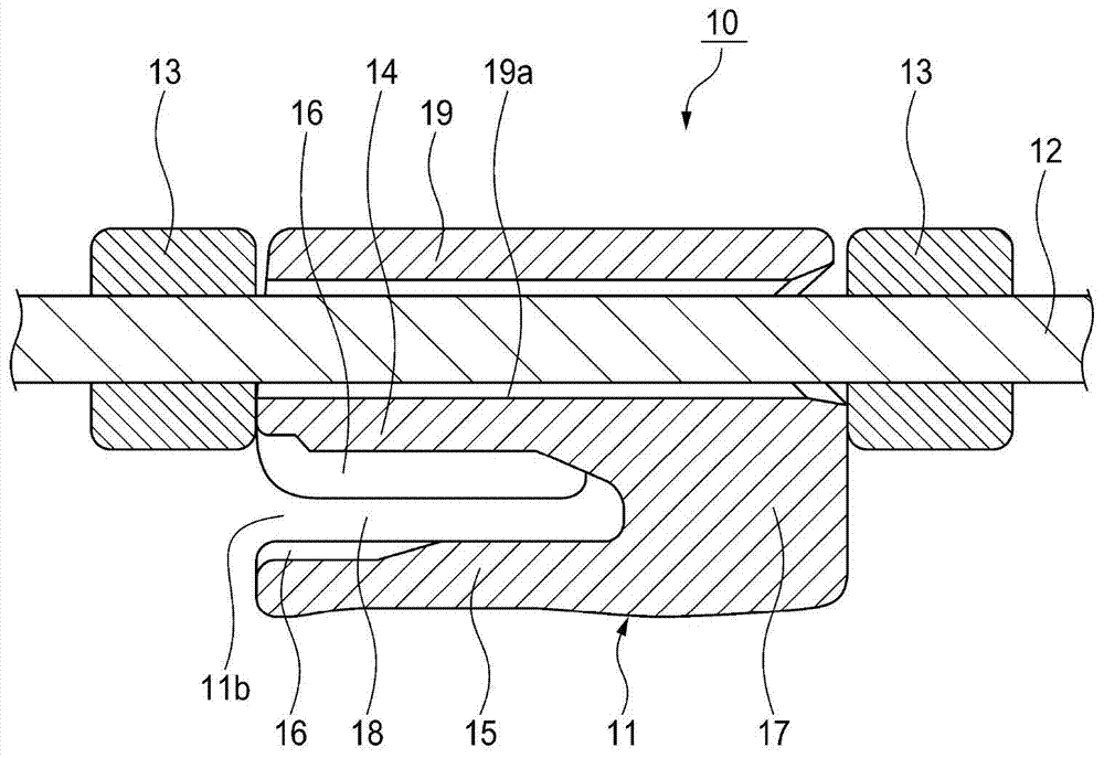
[0056] First, refer to Figure 1 to Figure 5 A slider for a slide fastener according to a first embodiment of the present invention will be described.
[0057] Such as figure 1 As shown, the slider 10 for a slide fastener according to this embodiment includes: a main body 11, which tightens and releases the elements of a pair of left and right fastener stringers (fastener stringer) not shown; fixed to the main body 11 ; and a pair of front and rear fixing members 13 which are additionally configured relative to the main body 11 to fix the cord 12 to the main body 11 .
[0058] Such as Figure 1 to Figure 3 As shown, the main body 11 includes: an upper piece 14 and a lower piece 15, which are arranged parallel to each other and opposite to each other in the up-down direction; a pair of left and right flanges 16, which are along the sides of the upper piece 14 and the lower piece 15 and a guide column 17 connecting the upper piece 14 and the lower piece 15 at the front ends ...
no. 2 approach
[0066] will refer to Figure 6 to Figure 11 A slider for a slide fastener according to a second embodiment of the present invention will be described. Meanwhile, the same or equivalent parts as those of the first embodiment are denoted by the same reference numerals, and descriptions thereof will be omitted or simplified.
[0067] Such as Figure 6 to Figure 8 As shown, the slider 30 for a slide fastener according to the present embodiment includes a main body 11 , a string 12 , and a cover 31 configured additionally relative to the main body 11 to fix the string 12 to the main body 11 .
[0068] Such as Figure 7 to Figure 9 As shown, a substantially cuboid-shaped base 32 is integrally formed on the entire surface of the upper piece 14, and a substantially U-shaped cord receiving groove (cord receiving groove) for receiving the cord 12 is formed along the longitudinal direction at the center of the base 32 in the left-right direction. Department) 33. In addition, two prot...
no. 3 approach
[0075] Next, we will refer to Figure 12 to Figure 18 A slider for a slide fastener according to a third embodiment of the present invention will be described. Meanwhile, the same or equivalent parts as those of the first embodiment are denoted by the same reference numerals, and descriptions thereof will be omitted or simplified.
[0076] Such as Figure 12 to Figure 14 As shown, the slider 50 for a slide fastener according to the present embodiment includes a main body 11 , a string 12 , and a cover 51 configured additionally relative to the main body 11 to fix the string 12 to the main body 11 .
[0077] Such as Figure 13 to Figure 15 As shown, a substantially U-shaped cord receiving portion 52 is formed at a substantially central portion of the surface of the upper sheet 14 along the length direction, wherein the cord receiving portion has a pair of substantially rectangular wall portions extending in the length direction to receive the cord 12 . In addition, a protru...
PUM
 Abstract
Description
Claims
Application Information